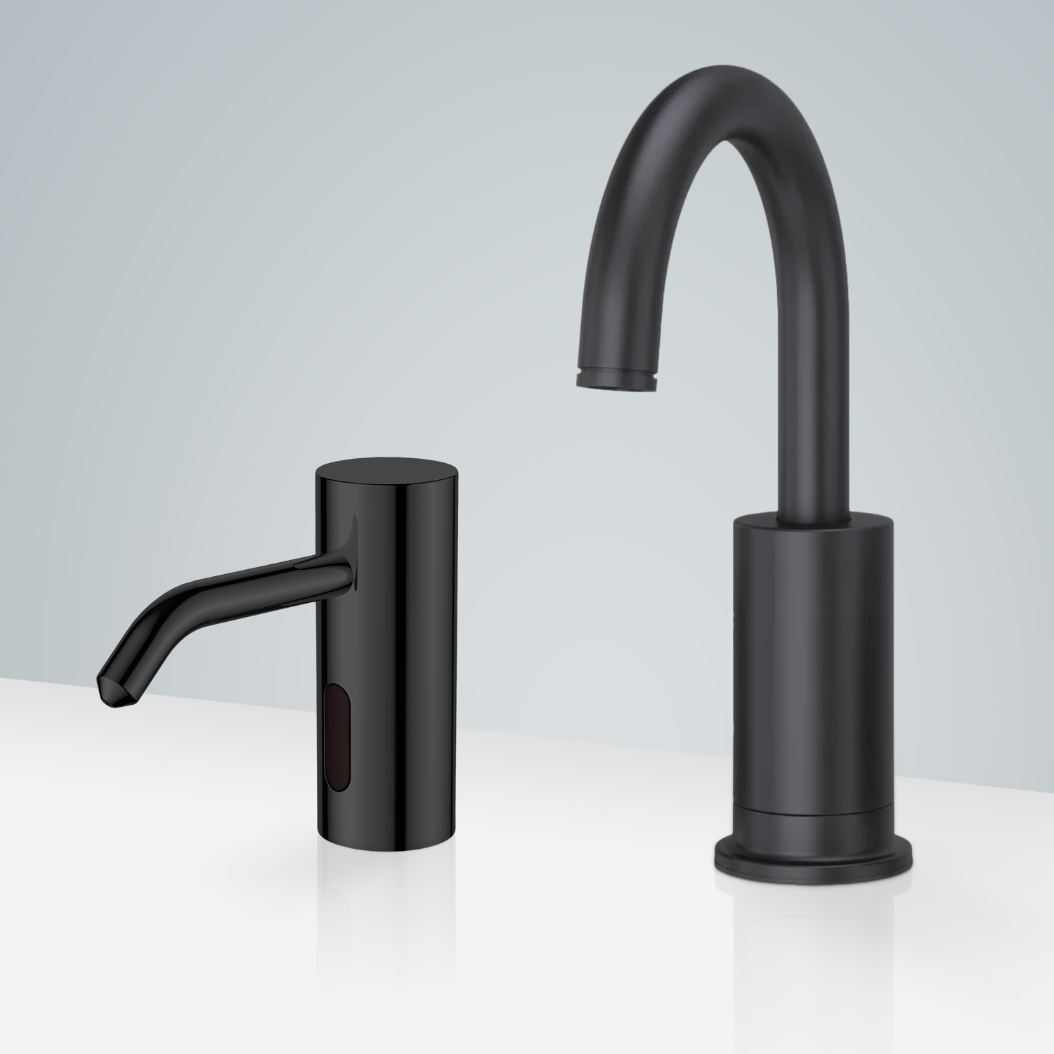
How to install Fontana Dax Oil Rubbed Bronze Commercial Touchless Motion Sensor Faucet & Deck Mount Automatic Liquid Soap Dispenser For Restrooms | FS18282
Easy step by steps Installation Instructions for Commercial Touchless Sensor Faucet & Soap Dispenser Combo
Before you begin, please read the installation instructions below. Observe all local building and safety codes.
Unpack and inspect the product for any shipping damages. If you find damages, do not install.
Please note all showers must be installed by a professional and certified plumber otherwise warranty might be voided.
sensor
Sensor Faucet Installations Instructions
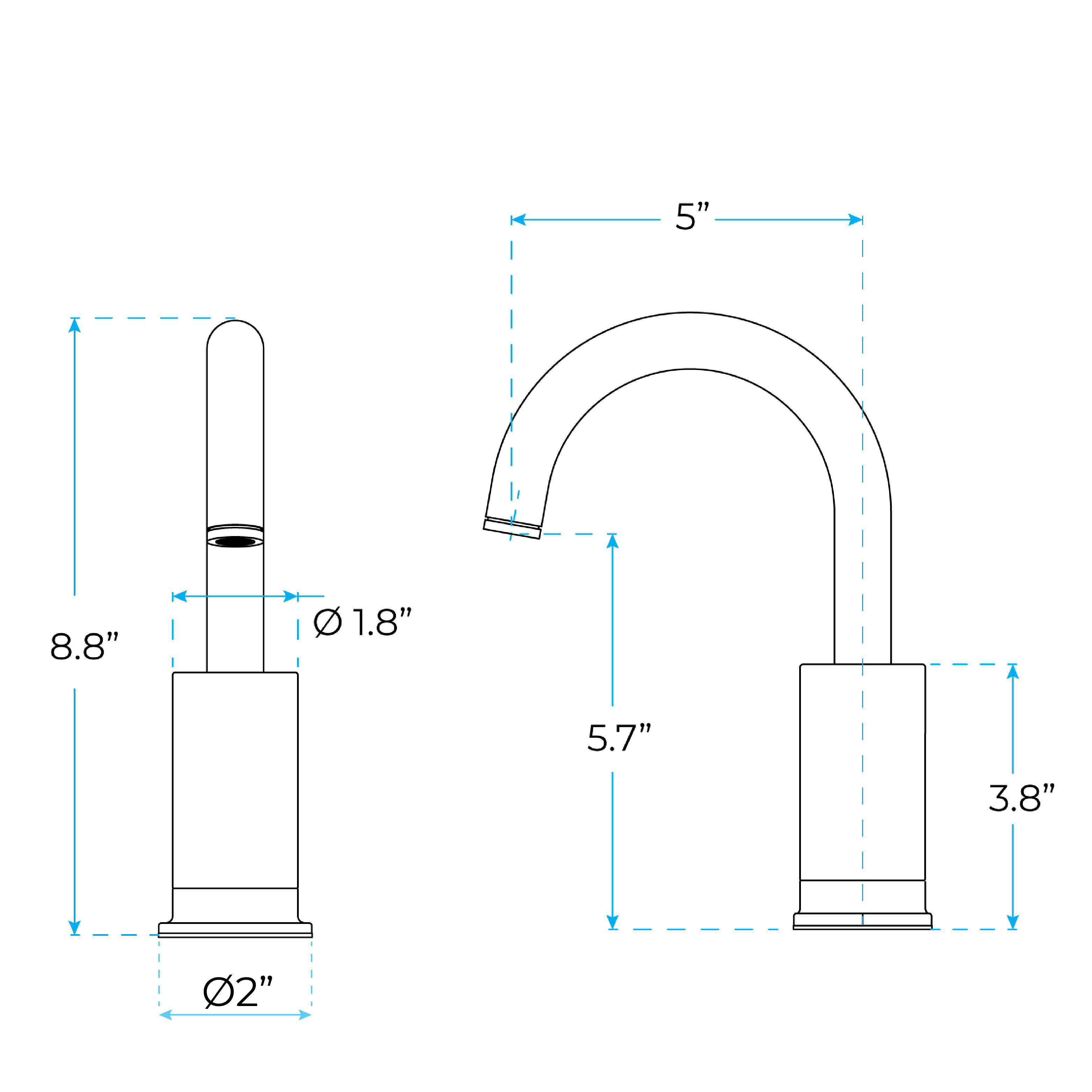
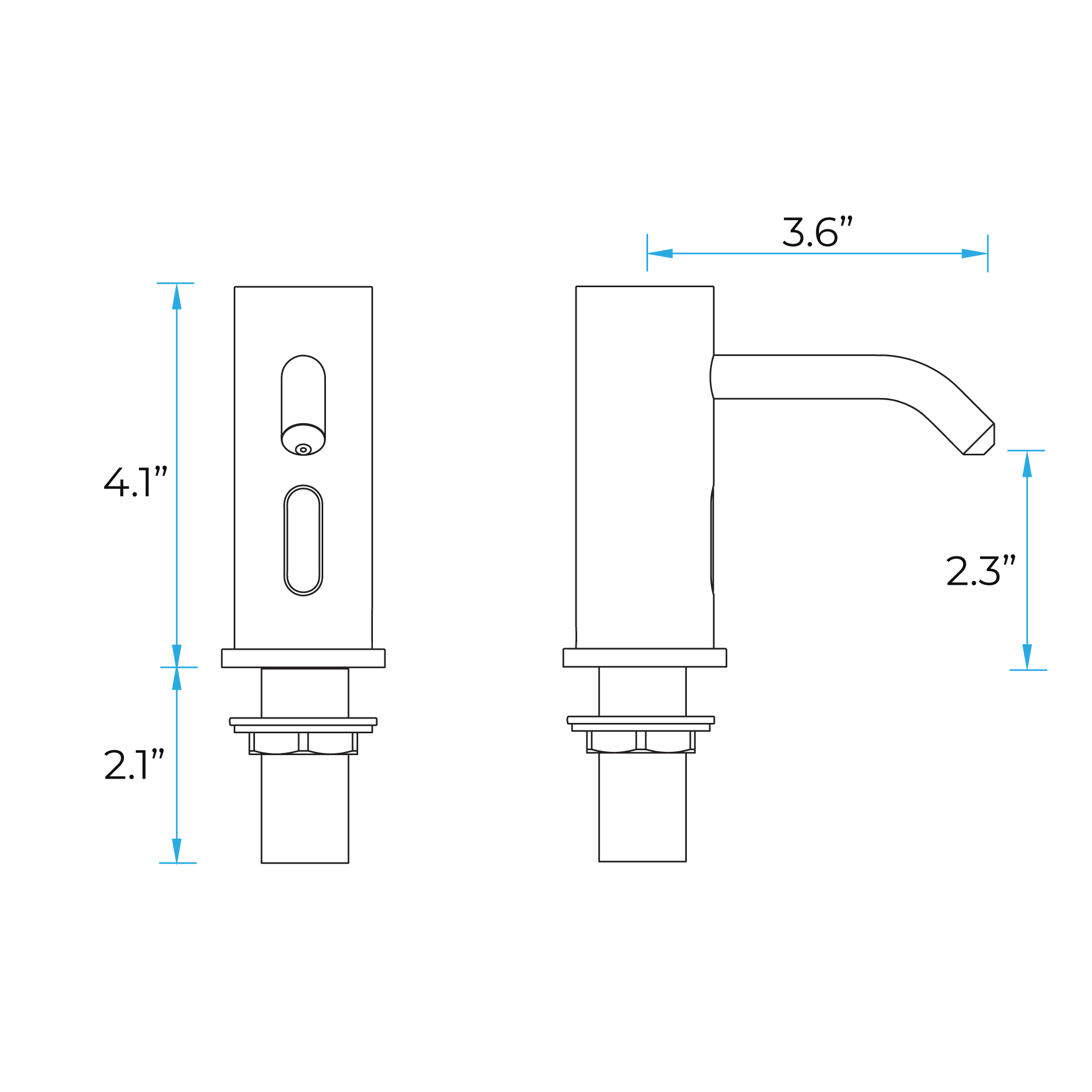
Size:
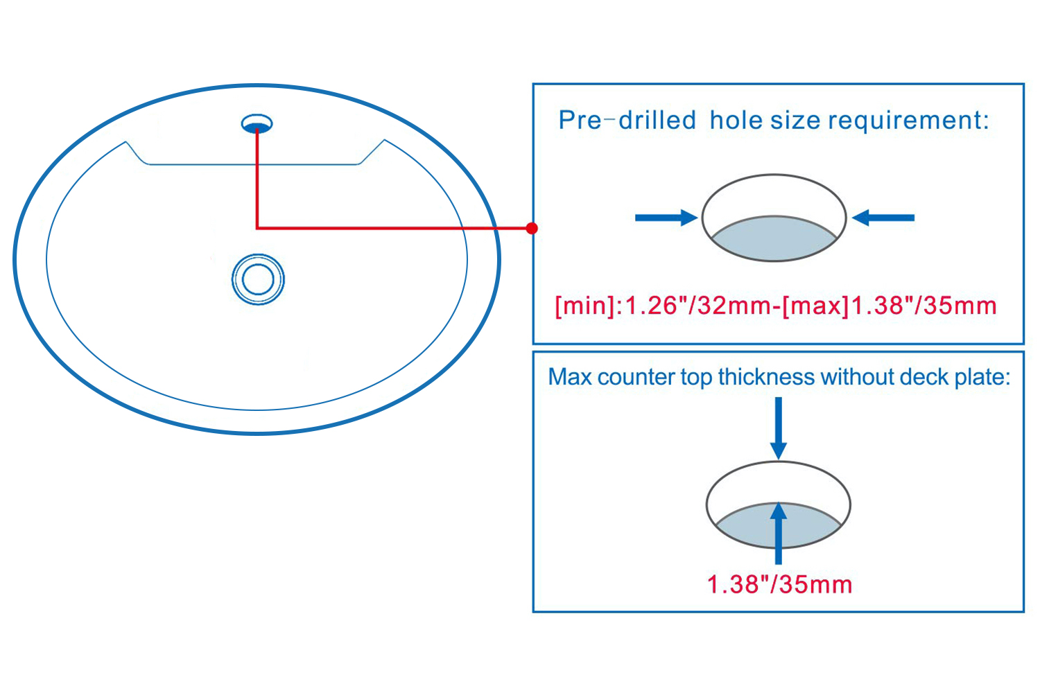
Hole size:
Battery (DC 6V) Only Control Box
Step 1:
Step 2: (Hot & Cold Connection)
infrared
Battery (DC 6V) & AC 220V Control Box
Step 3:
Step 4:
Step 5:
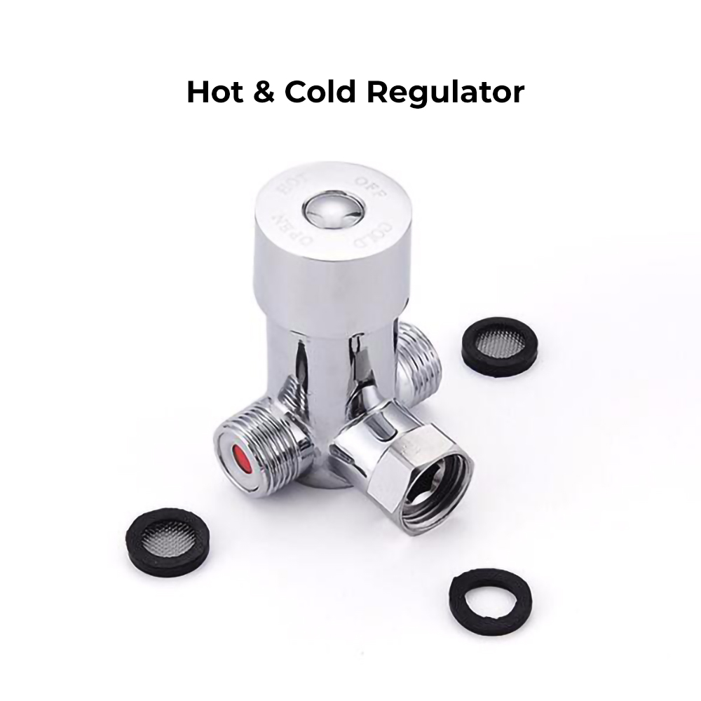
Step 6: Hot & Cold Regulator
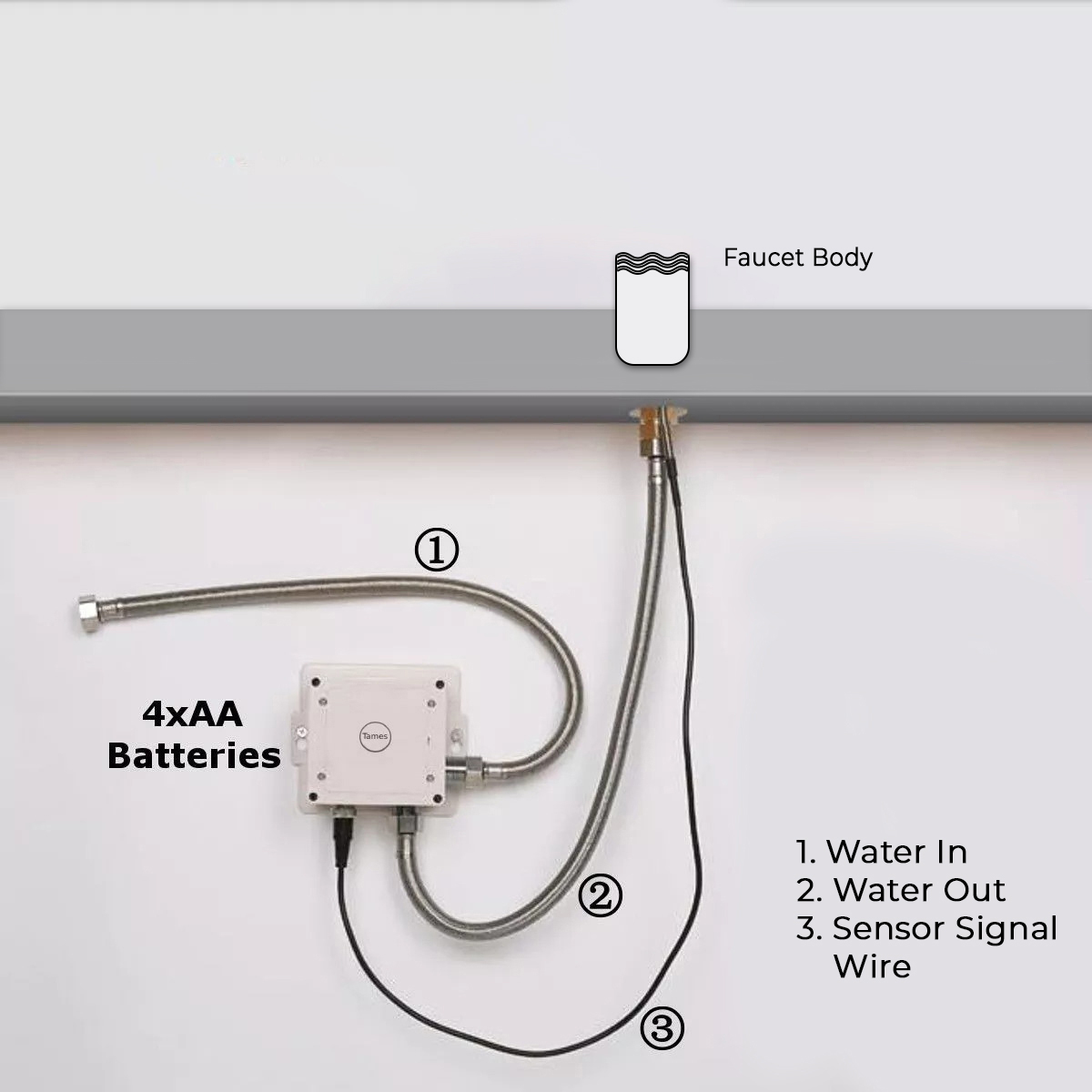
Step 7: (Correct way for Hose)
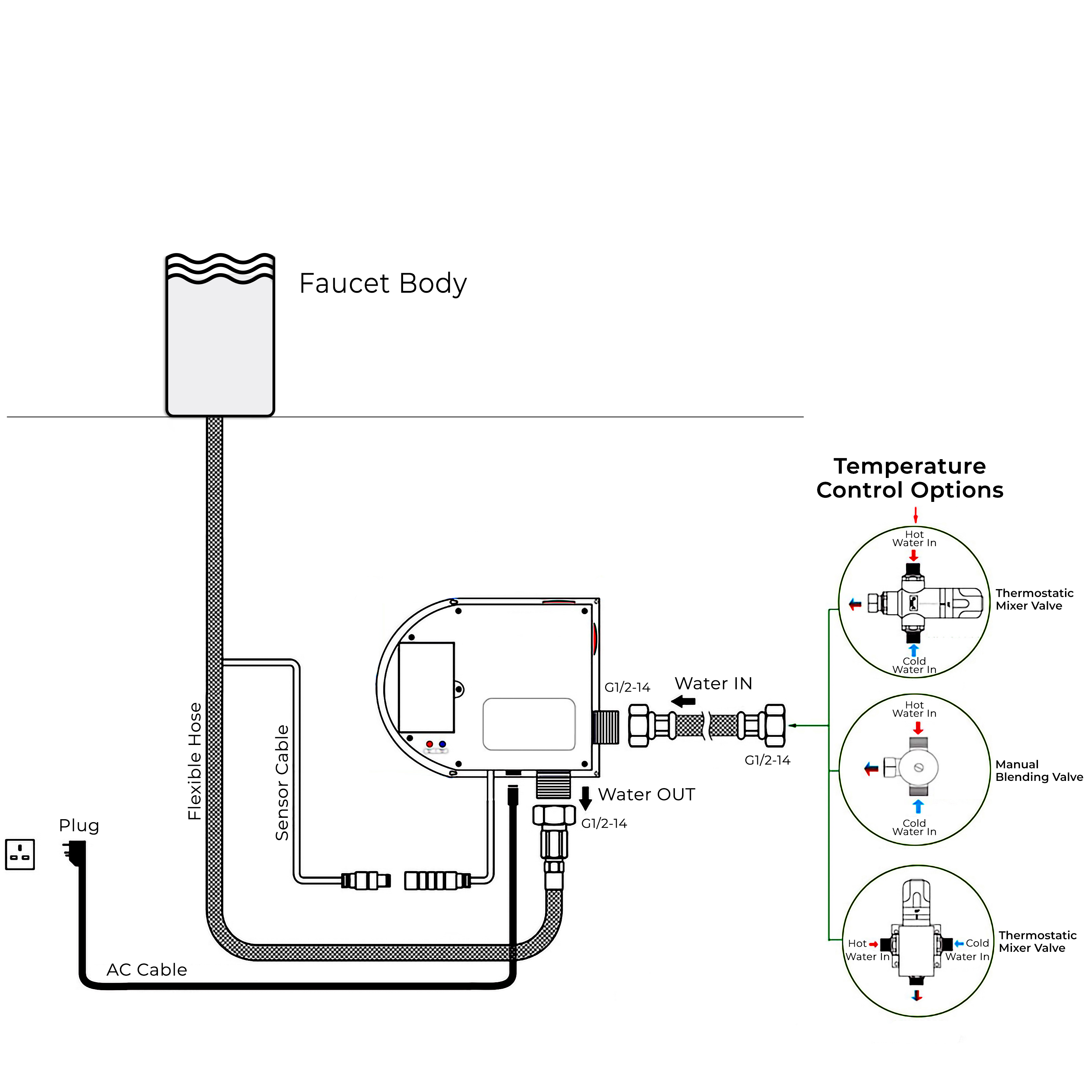
1. Screw the hose into the corresponding screw-hole of the faucet body. Fix the o-ring into the bottom groove of the faucet body.
2. Insert hose, threaded pipe and data cable through the drilled hole of the countertop. Put rubber washer and metal washer onto the threaded pipe, screwing in mounting nut. Adjust the faucet body correctly and tighten the mounting nut with screws.
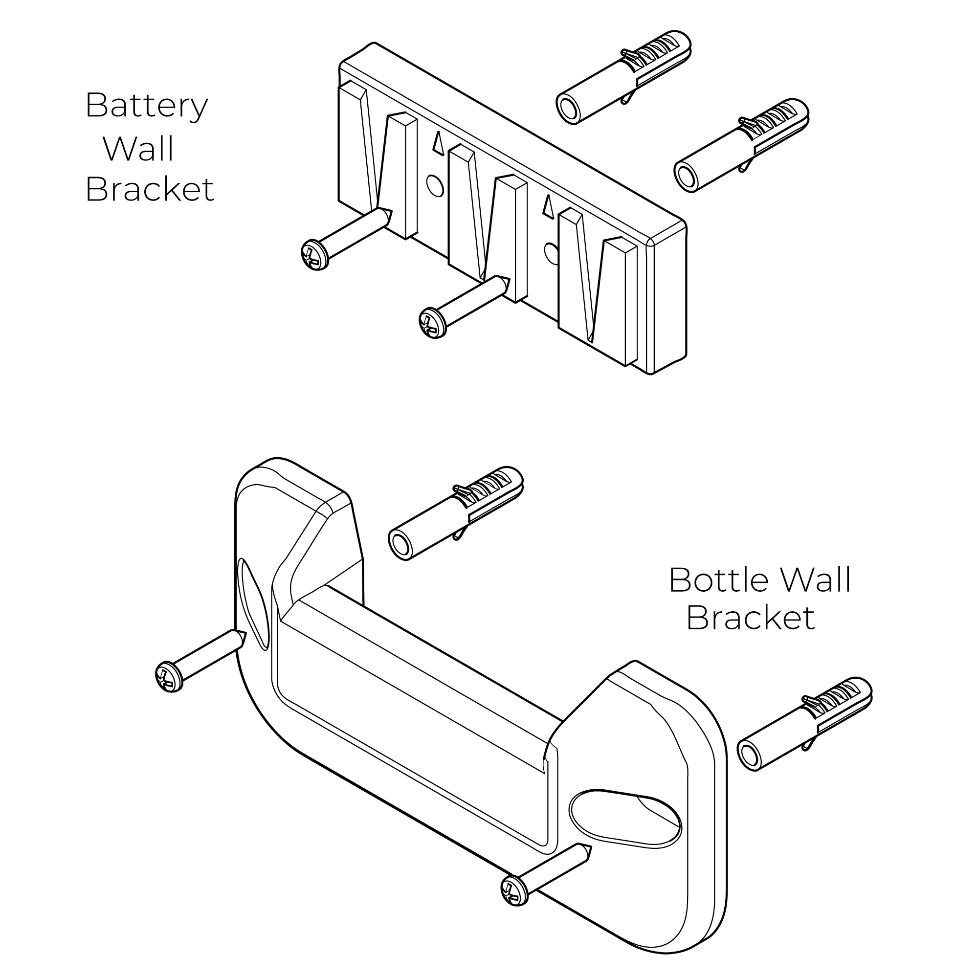
3. Install the control box to the wall and fix it with screws.
4. Add the rubber washer and screw supply elbow to the control box.
5. Add rubber washers and connect water lines to the hot and cold inlets of the supply elbow. Then connect the hose to the water outlet and insert data cable into the control box and plugin.
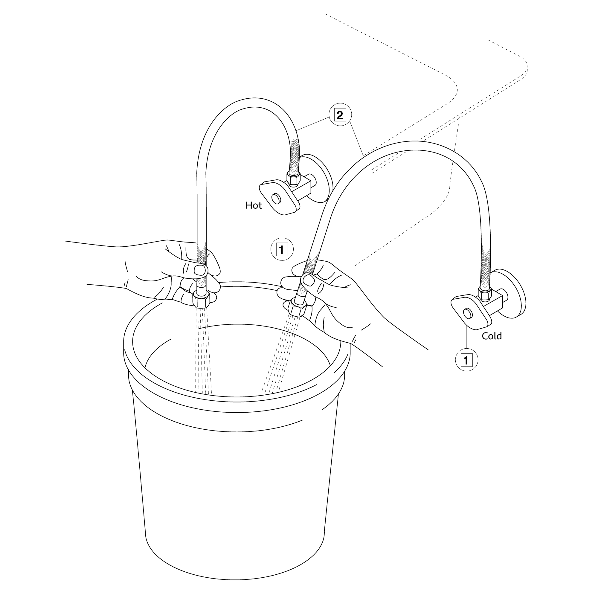
6. Make Connections to water supplies. Turn on hot and cold water supplies and flush water lines into a container for one minute. Important: This flushes away any debris that could cause damage to internal parts.
7. Connect waterlines to angle stops. Turn on the angle stops and check for leaks (DO NOT TURN FAUCET ON).
8. Turn the faucet on for 1 minute to flush any debris.
Flexible Connecting Hose Care must be taken when connecting the flexible connection hose from the power supply box to the spout to ensure it does not bend sharply and kink or twist. See above for recommended ways to fit the flexible connecting hose.
Important: Failure to follow these guidelines may result in poor performance and damage to the flexible connection hose.
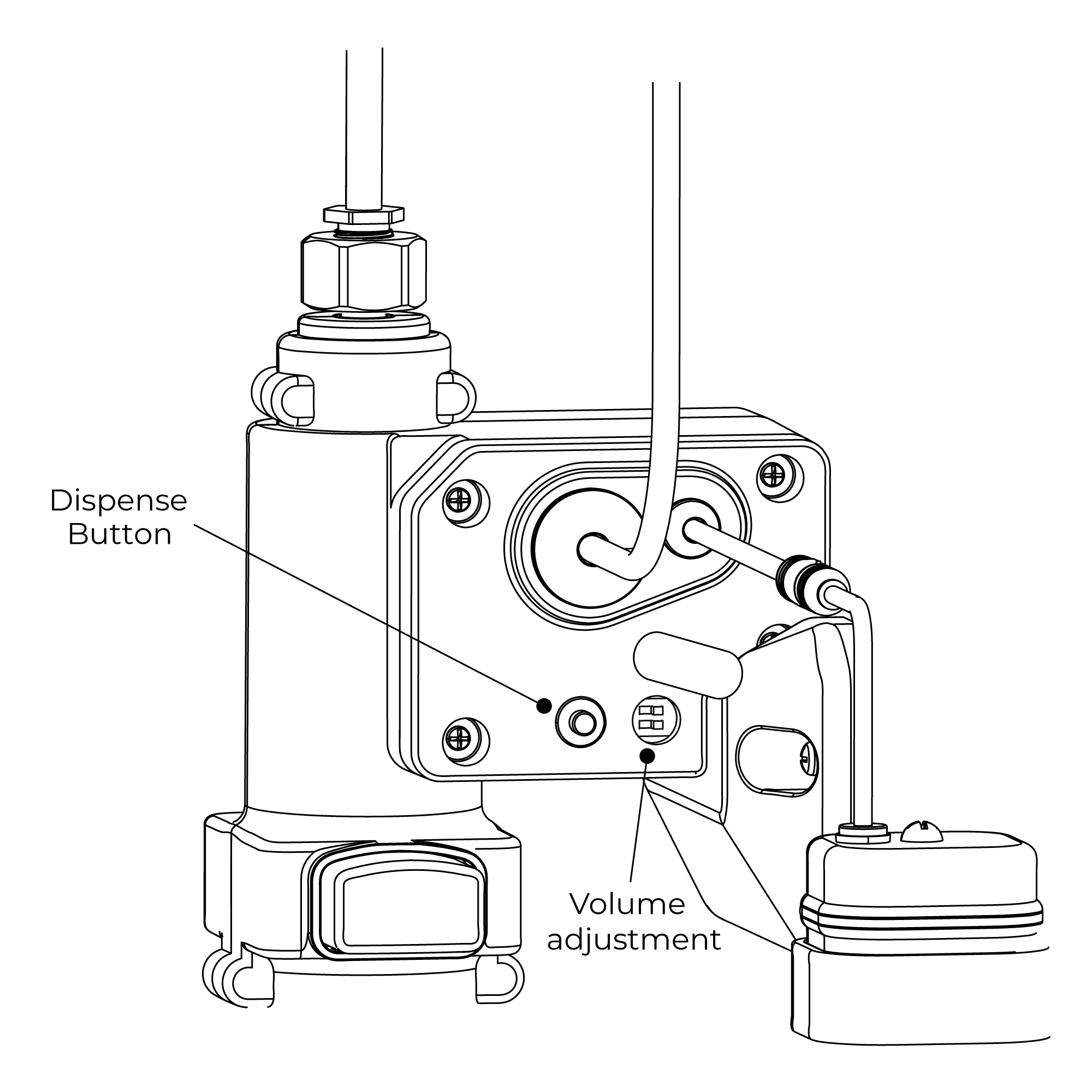
Washing Time: 30-second (Default/ Adjustable).
Water Pressure: 0.5 - 7.0 KGS/cm, 10 - 125 psi
Power Supply: AC110V And DC6V (batteries not included)
Battery Life Expectancy: 200,000 cycles
Solenoid Valve: 6 Volt magnet latching
Working Water Pressure: 1 PSI -100 PSI
Supply Inlet Size: 1/2" NPT Male
Water Temperature Control: Built-in
Sensor Type and Location:Active Infrared, Deck mount
Sensor Microprocessor: Digital, Pug, And Play
Sensing Range: 2†to 6â€
Response Time: 0.3 Second
Shut-Off Delay Time: 2 Seconds
Maximum Running Time: 60 Seconds
Particle Filter Size: 50 Mesh
Aerator: 2.2 GPM Standard
Control Box Installation Instructions
Step 1:
Step 2:
control box
Step 3:
Step 4:
Size: 5" x 5"
AC Cable
Step 5:
Step 6:
Inserting Batteries Your infrared spout is supplied with a back up battery pack (batteries not included). In the event of a power failure the batteries will override the mains power supply to ensure the spout continues to function.
Before fitting the power supply box into position on the wall/floor, batteries (not included) will need to be fitted.
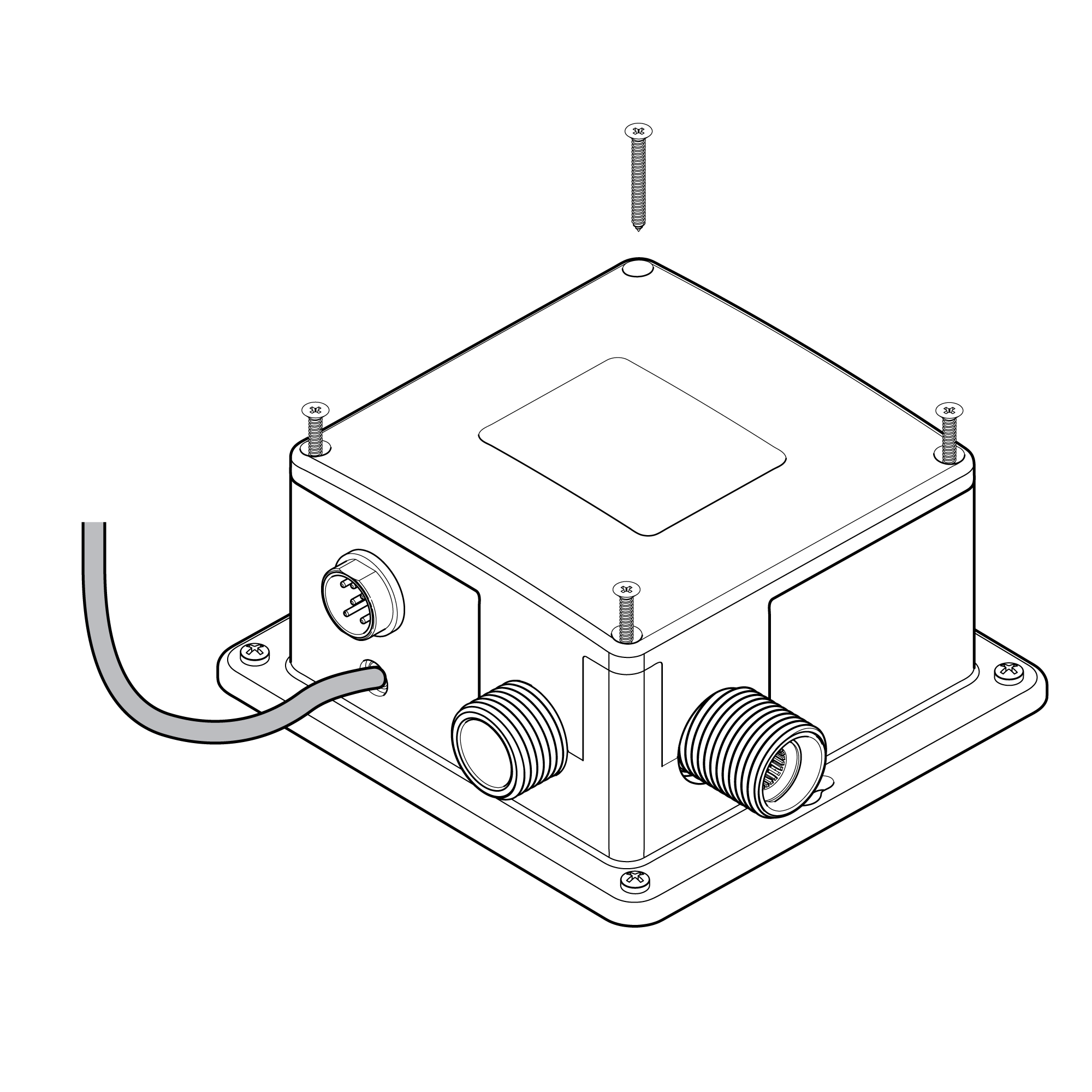
1. Remove Power Supply Box Cover Remove all four screws in each corner of the power supply box and remove the cover.
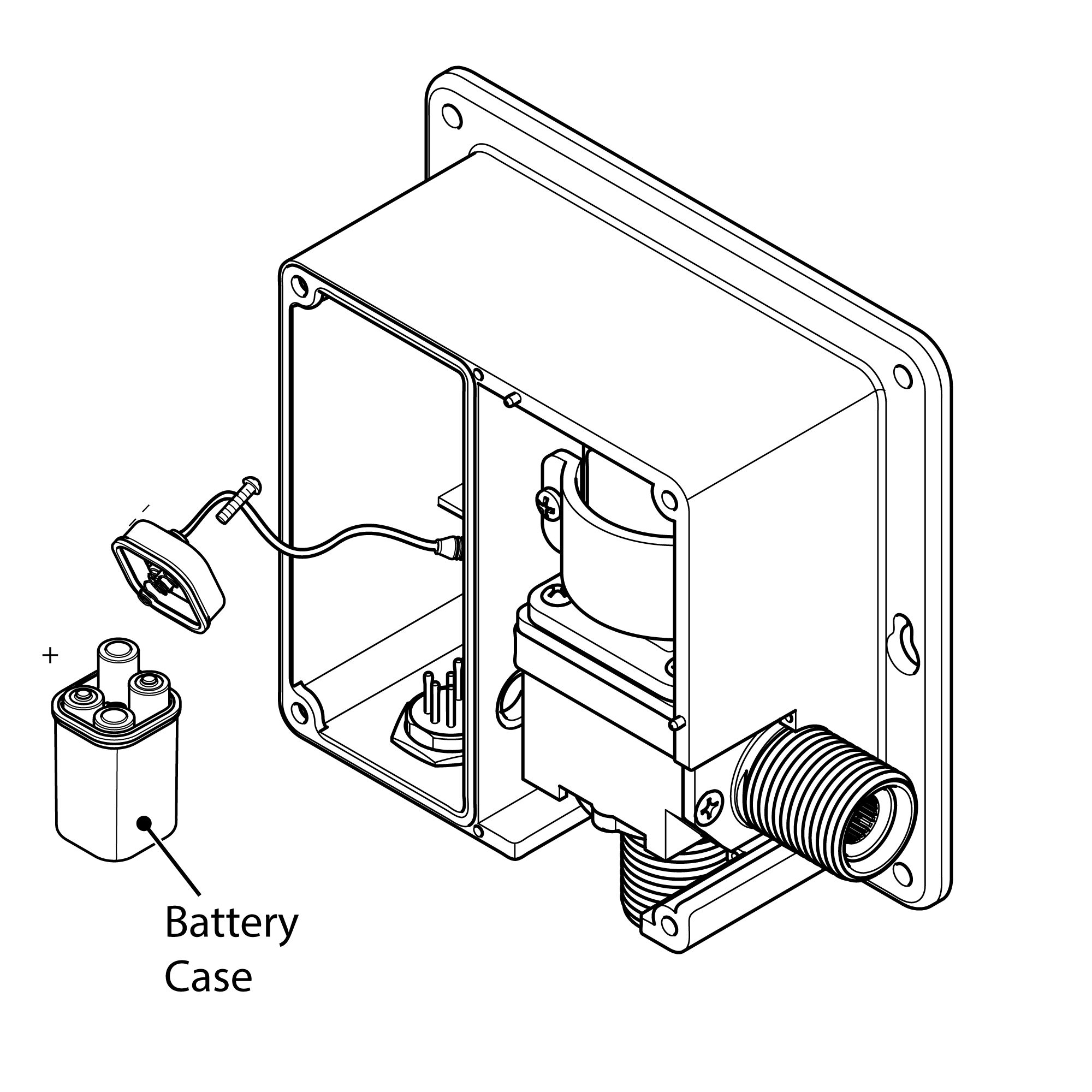
2. Remove Battery Box Remove the battery case from the power supply box and remove the screw in the center of the case.
3. Insert Batteries Insert 4 x AA batteries (not included) into the battery box ensuring they are inserted the correct way. Note: Only use 1.5V AA (LR6) Alkaline batteries (preferably => 2000mAh for good battery life).
4. Replace Battery Box Replace the battery case cover. Replace and tighten the screw. Insert the battery case back into the power supply box.
5. Replace Power Supply Cover Replace the power supply cover and tighten all 4 screws ensuring they are all fully tightened.
Installation - Electrical Connections
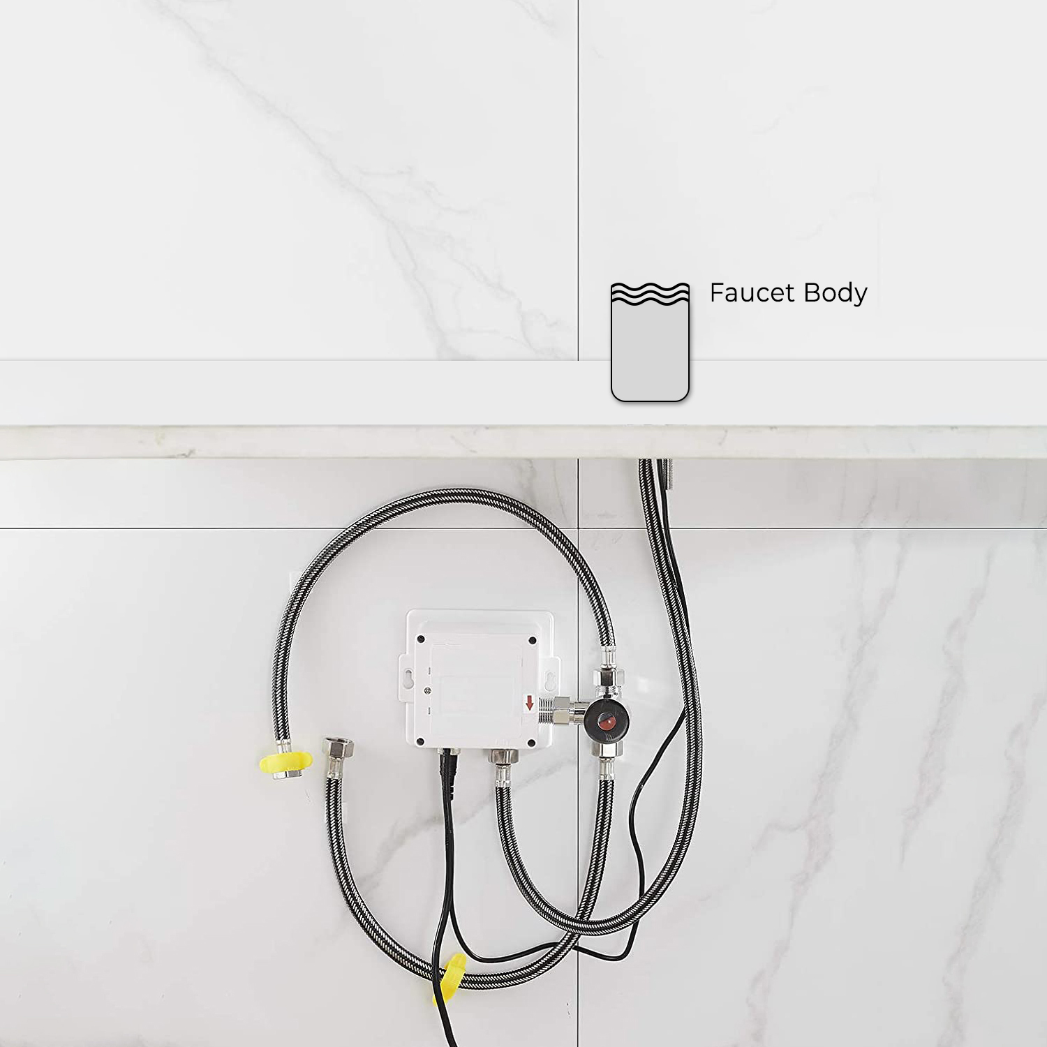
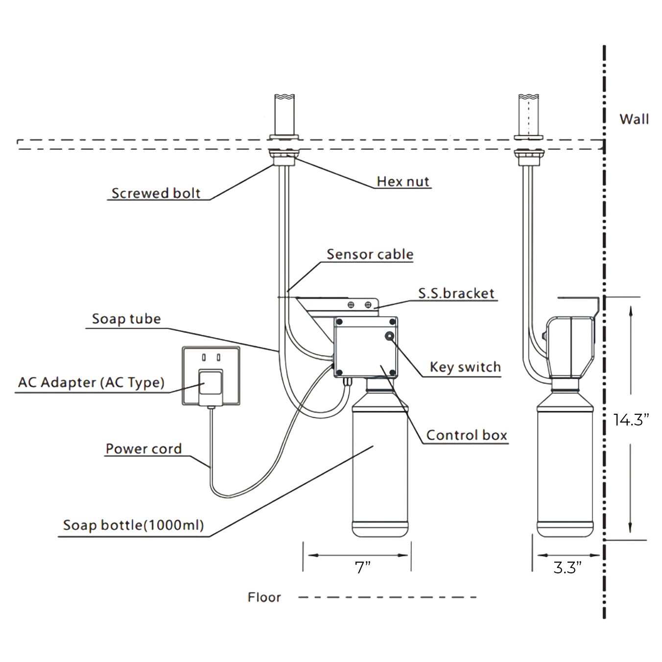
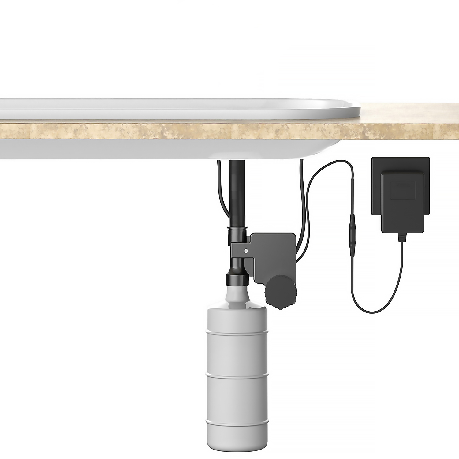
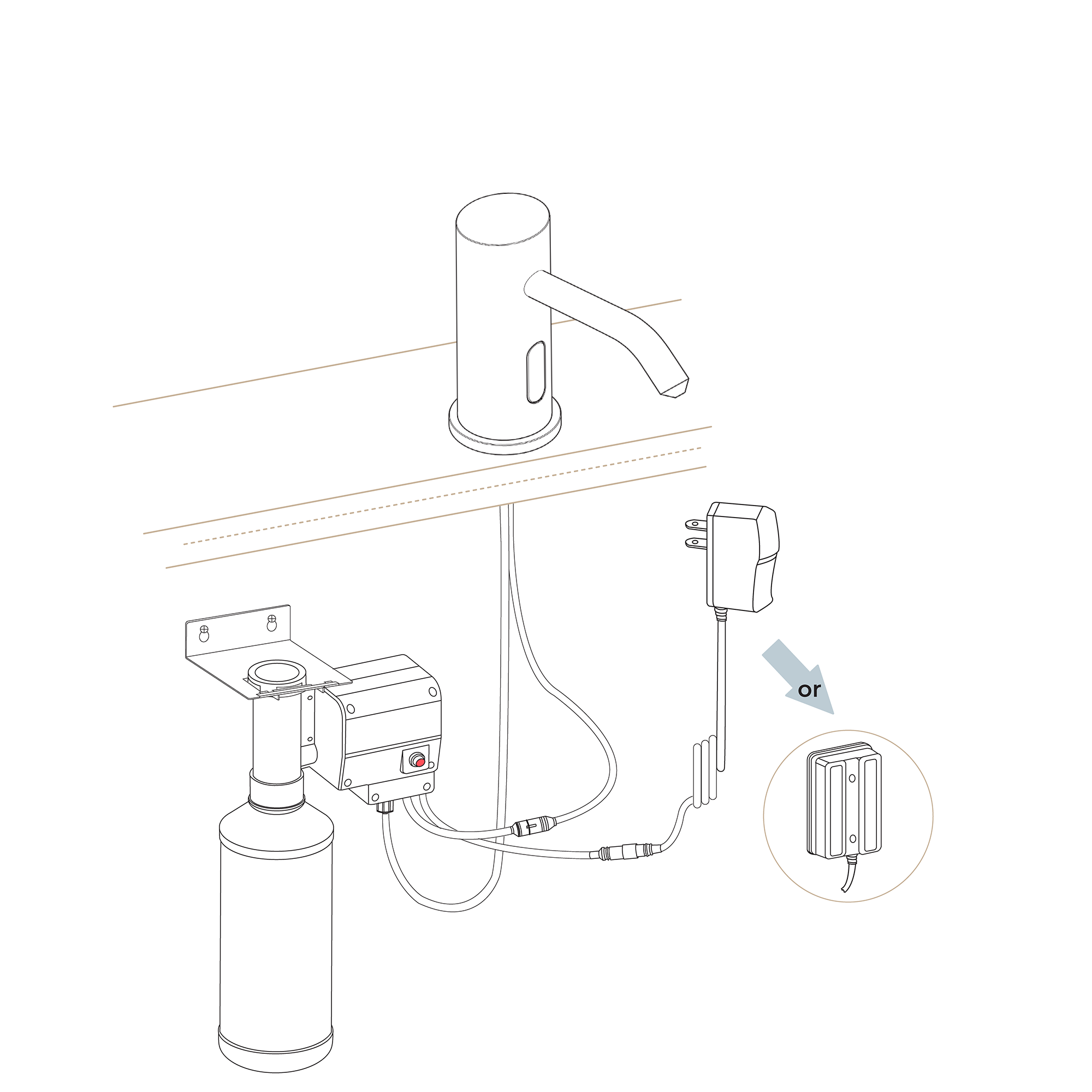
1. Position Power Supply Box Position the power supply box onto the wall surface below the sink/work surface where it is easily accessible.
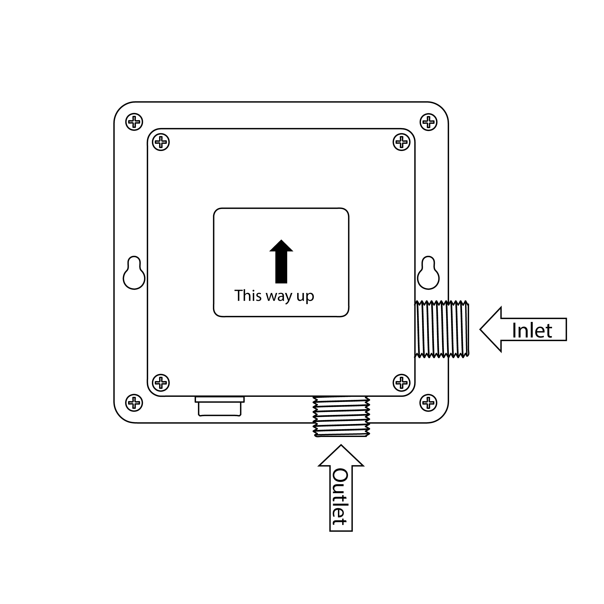
Note: Ensure that the power supply box is fitted the correct way up (see opposite) and that the flexible hose will reach from the underside of the spout to the power supply box.
Using suitable fixings for the wall type secure the power supply box to the wall.
2. Connect Power Supply Cable Before starting any electrical work ensure the power supply is isolated. Wire the electrical power cable into a switched fused spur off the ring main. The blue wire should be wired to the neutral connection and the brown wire should be connected to the live connection.
Important: The power supply box must be permanently connected to the fixed wiring of the mains supply using the factory supplied power cable.
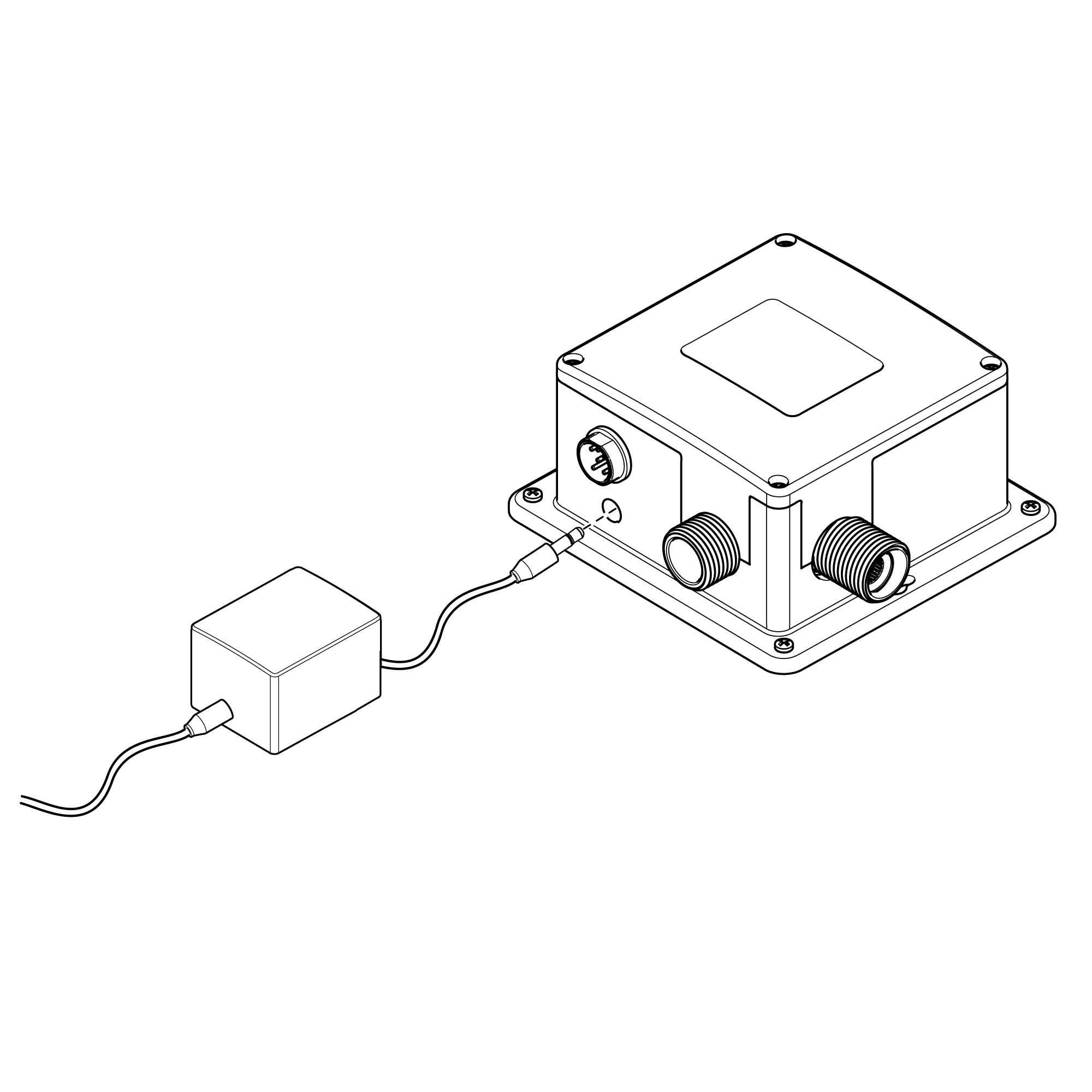
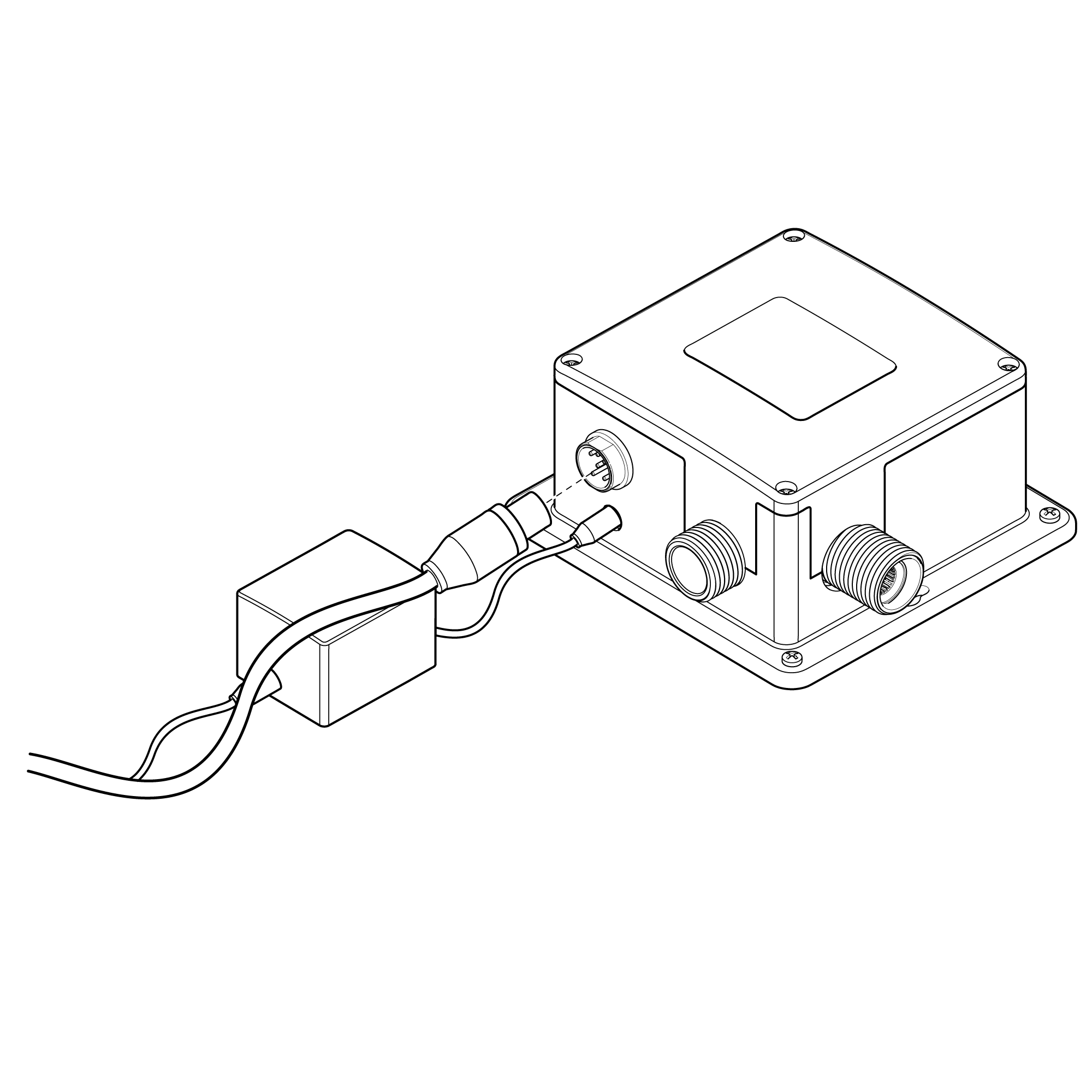
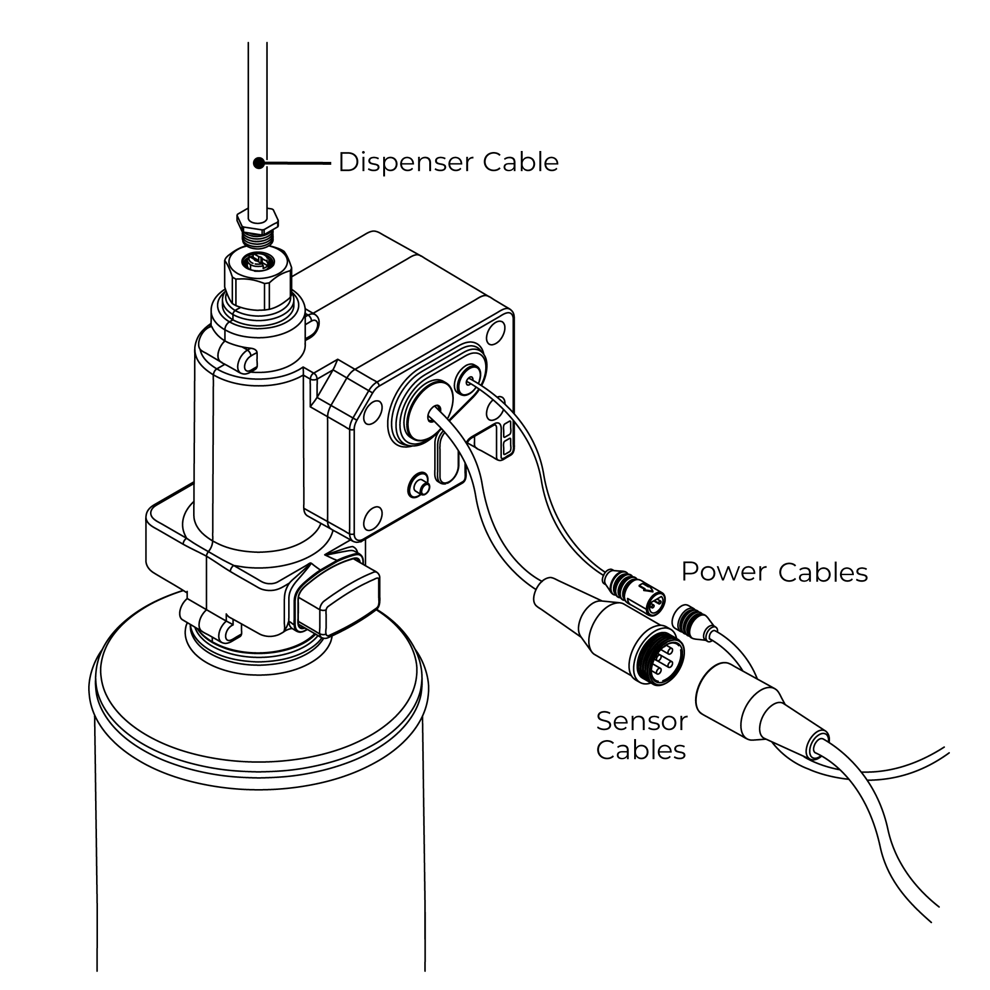
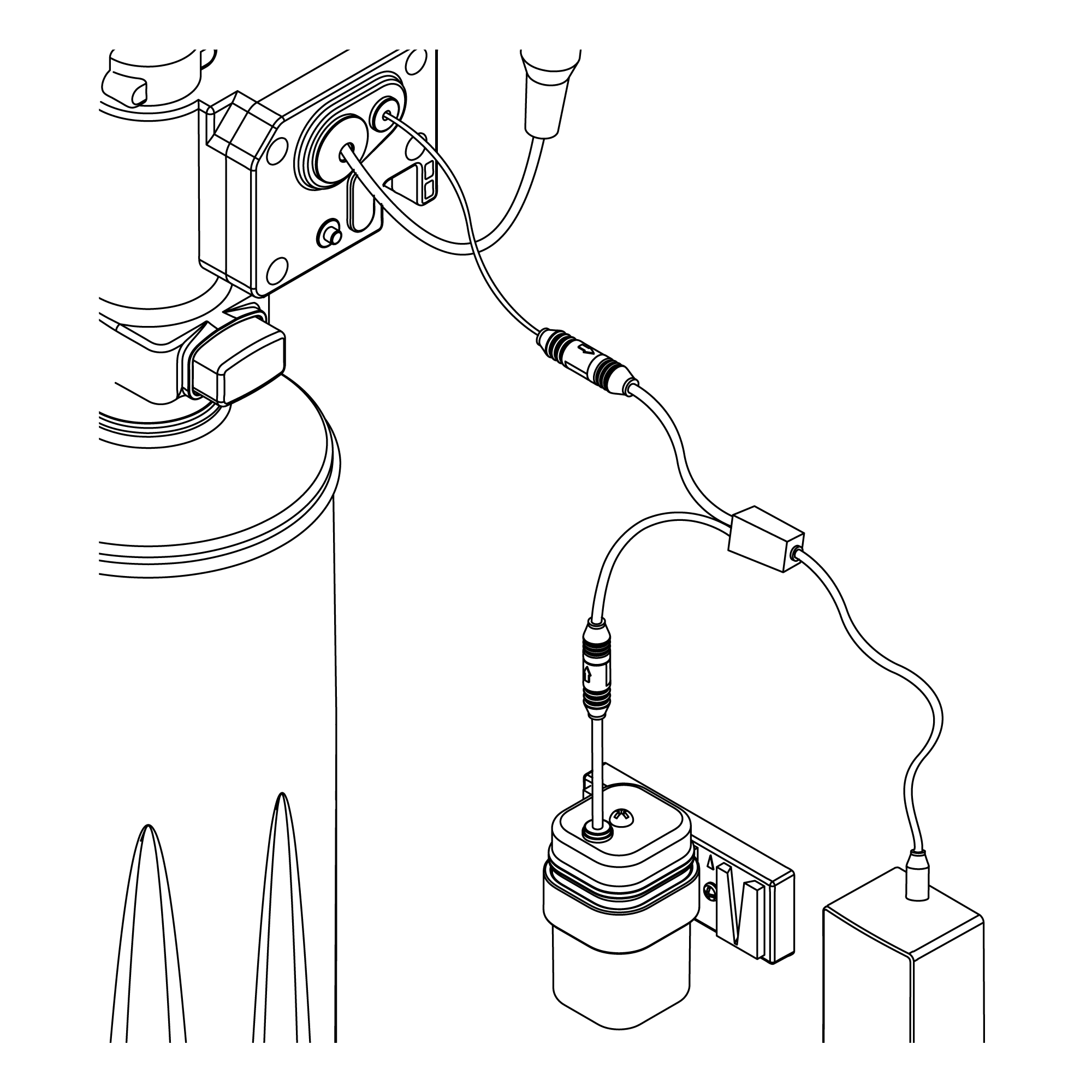
3. Plug In Power Cable Plug the power cable into the power supply box.
4. Connect The Sensor Cable Plug the sensor cable from the spout into the power supply box to activate the infrared senor.
Installation - Water Connections
Connecting Water Supply A blended water supply is required to the inlet of the power supply box. Before connecting the water supply to the power supply box flush through the pipework to ensure removal of debris. Once flushed through turn off the mains water supply and close any isolating valves.
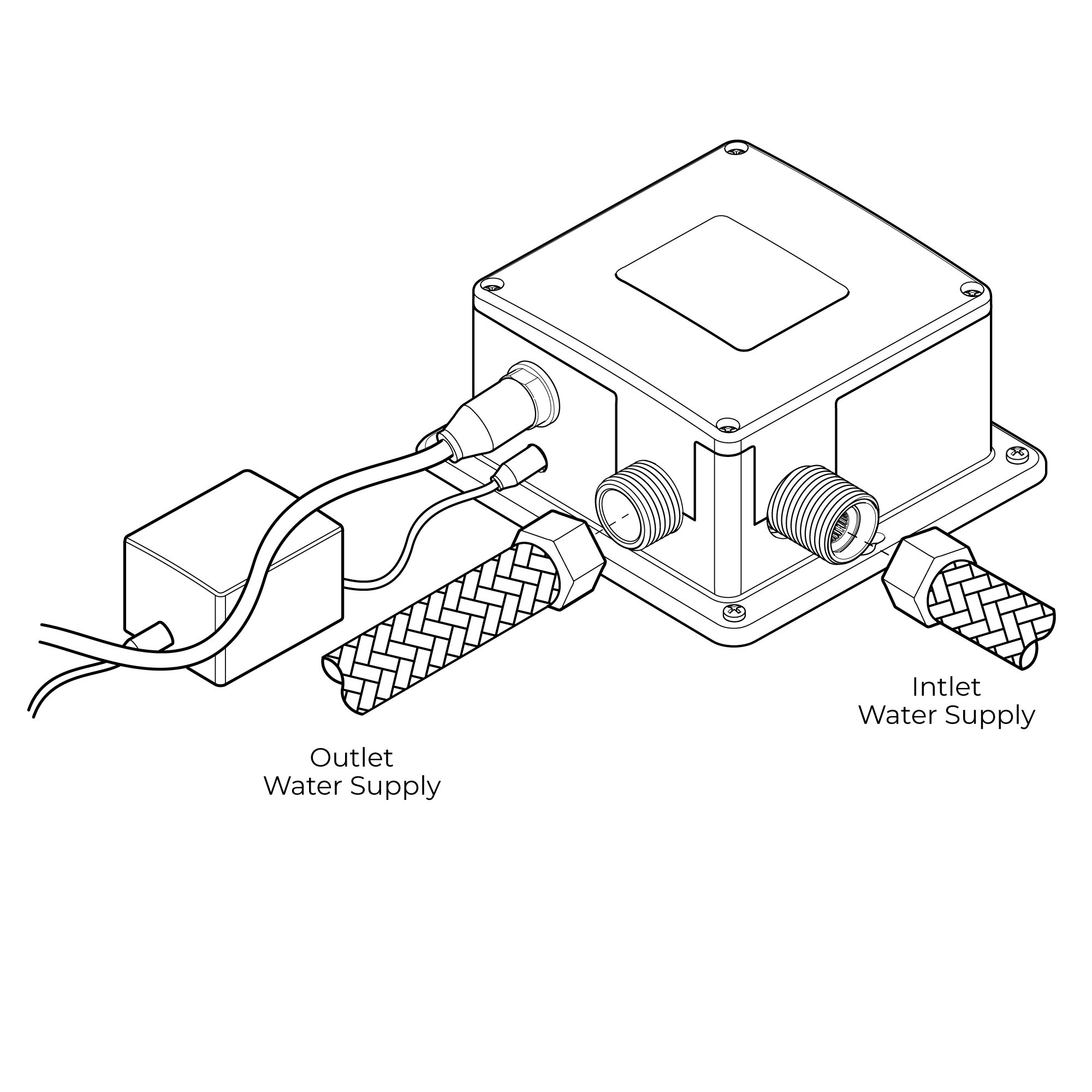
Inlet Connection The inlet connection on the power supply box is a 1/2” BSP male threaded connection. Connect a 1/2” BSP female connector to the inlet connection ensuring a suitable sealing washer is used to create a water tight connection.
Outlet Connection The outlet connection is a standard 1/2” BSP male threaded connection. Connect the flexi hose (supplied) to the outlet connection, ensuring it is tightened fully.
Sensing Range: 0-8 cm Activation Time: 0.5-1s Power Supply: AC: 230V DC: 1.5V (4 x AA alkaline batteries - Not Supplied) Bottle Capacity: 1.6 litres Ambient Temperature: Normal Temperature Viscosity of liquid soap: 100-3500cp (mpA · s)
Features:
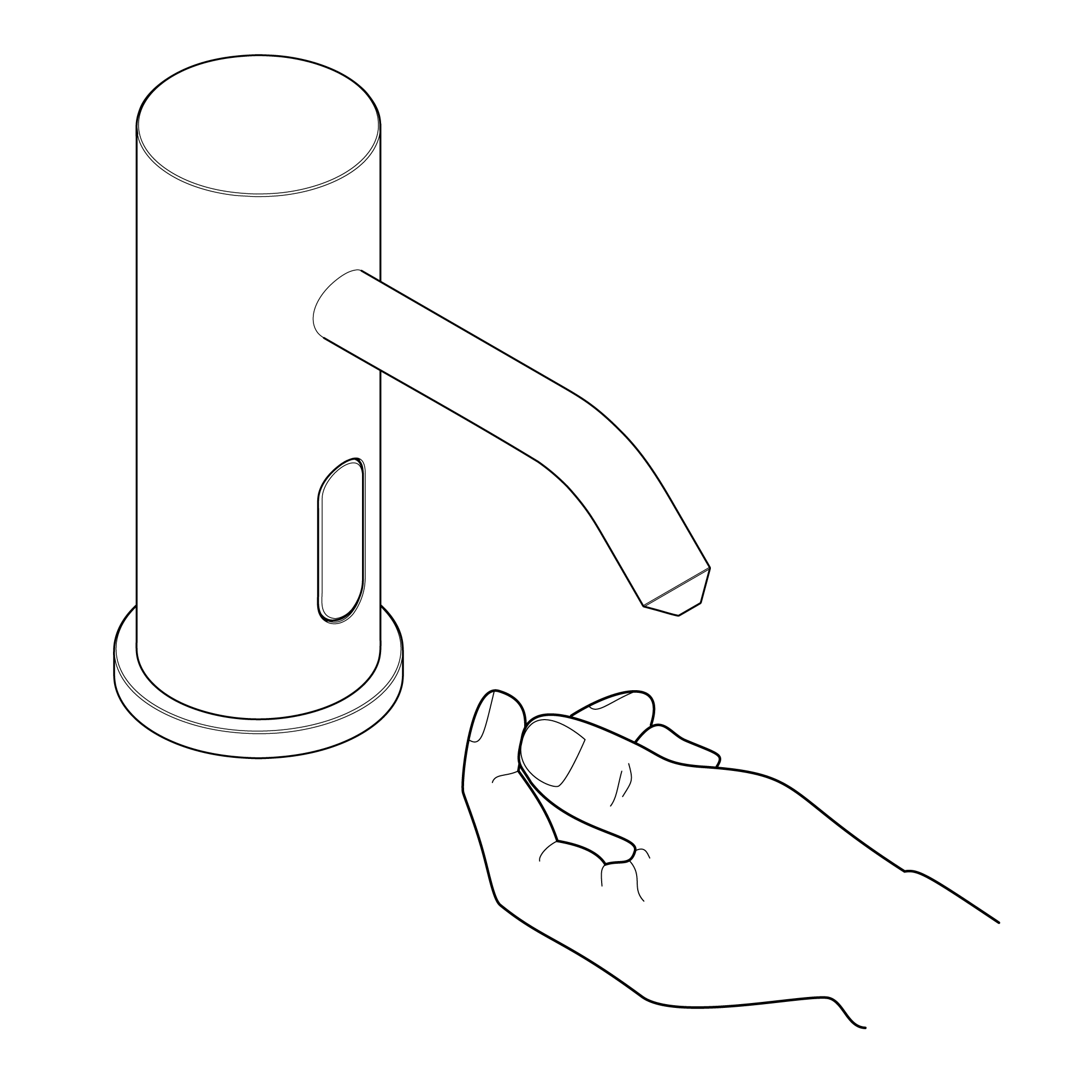
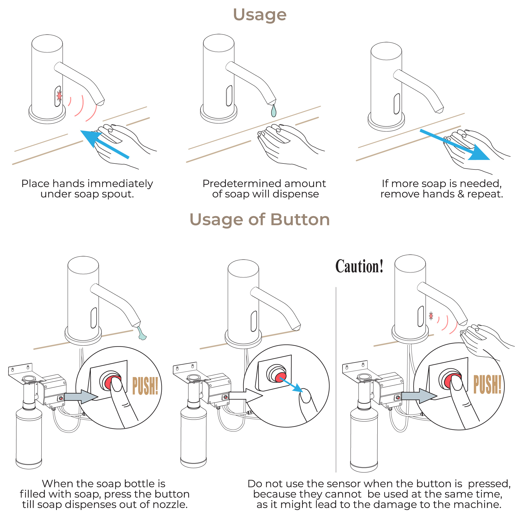
More Hygienic The proximity sensor removes the need to touch the spout, reducing the spread of germs and reducing the chance of cross-infection.
Battery Override Your infrared soap dispenser is supplied with a backup battery pack. In the event of a power failure, the product will automatically switch to battery-operated mode to ensure the spout continues to function.
Low Battery Warning When the batteries run low and the power falls below 3.9V the sensor light will flicker to indicate the batteries are running low and need replacing. When the batteries are exhausted the sensor light will not light up.
Electrical Connections
Regulations: The electrical installation must be carried out in accordance with the national electrical regulations and installed by a qualified person.
Safety: In the interests of electrical safety a 30 mA residual current device (R.C.D not supplied) should be installed in the supply circuit. This may be part of a consumer unit or a separate unit. Before starting work on the electrical supply ensure the power supply is isolated.
DO NOT allow the supply cord to contact hot surfaces. The cord should be safely routed and secured by cable clips.
Connections: The power supply must be permanently connected to the fixed wiring of the mains supply using the factory fitted supply cord, via a switched fused spur off the ring main. The wires in the mains lead are coloured in accordance with the following code: Blue: Neutral Brown: Live
As the colours of the wires in the mains lead of this appliance may not correspond with the coloured markings identifying the terminals in your connection unit proceed as follows;- The wire which is coloured blue must be connected to the terminal which is marked with the letter ‘N’ or is coloured black. The wire which is coloured brown must be connected to the terminal which is marked with the letter ‘L’ or is coloured red.
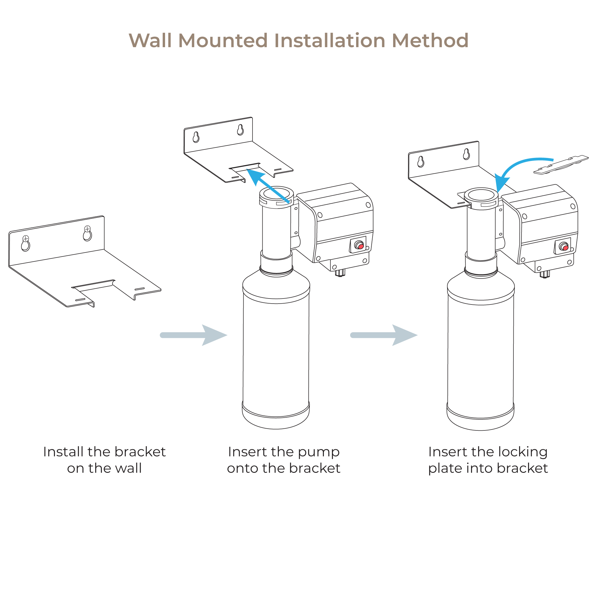
Installation
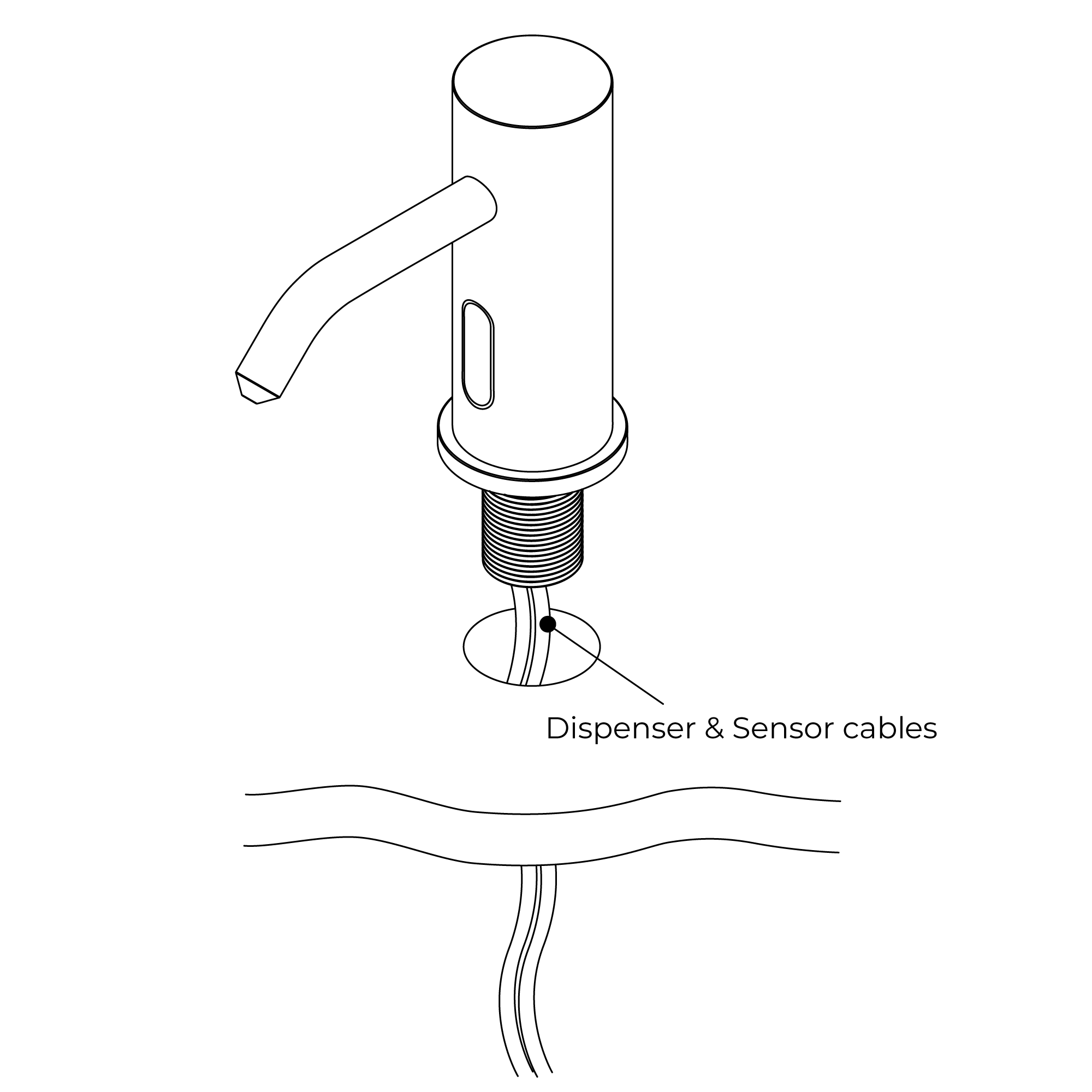
1. Fit The Spout Fit the spout to the sink/basin ensuring the dispensing cable and sensor cable are threaded through the hole in the sink/basin.
2. Secure Spout to Sink / Basin Screw the metal back nu