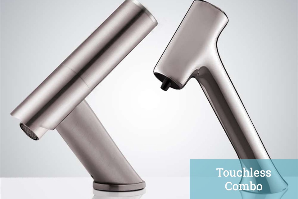
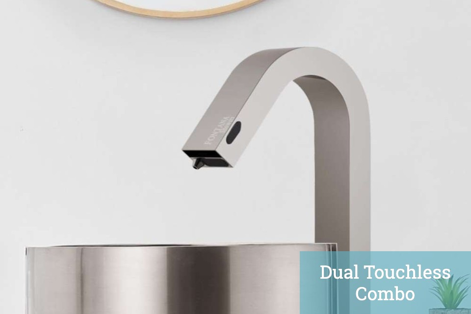
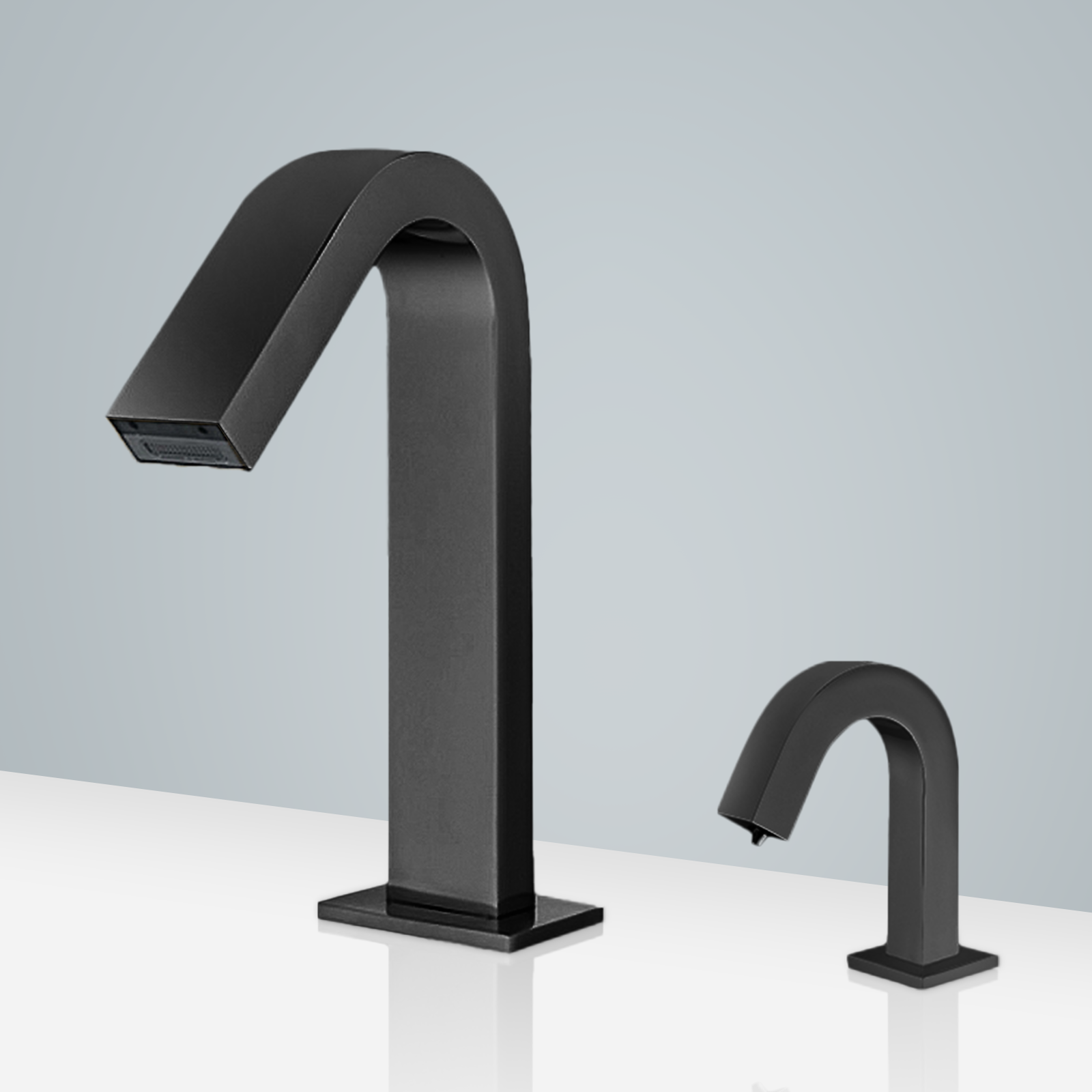
How to Install Fontana Commercial Automatic Dark Oil Rubbed Bronze Motion Sensor Faucet & Automatic Soap Dispenser | FST9879B
Easy step by step Installation Instructions for Commercial Sensor Faucet & Automatic Soap Dispenser Combo
- Before you begin, please read the installation instructions below. Observe all local building and safety codes.
- Unpack and inspect the product for any shipping damages. If you find damages, do not install.
- Please note all showers must be installed by a professional and certified plumber otherwise warranty might be voided.
|
sensor
|
|
Automatic Sensor Faucet Installation Instructions
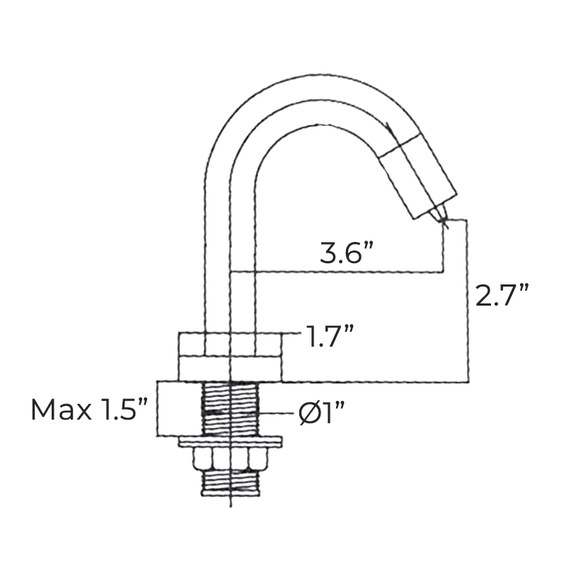
Size

|
|
Power: DC 2 pieces of AA size alkaline batteries
AC 220V, 50/60 Hz
Senser Duration: Less than 0.5s
Shut-off Delay: 0.5~1 s
Sensing Distance: Automatic adjustment
Flow Rate: No more than 2.0L/min at 0.3 MPa.
Overtime Flowing Control: Automatically stop flushing when the faucet senses an object for more than 1 minute continuously
Ambient Temperature: 1~55 °C
Supply Water Temperature: 0.5~71 °C
Supply Water Pressure: 0.05~0.86 MPa
|
|
|
|
|
|
Step 1:
|
sensor
|
Step 2:
|

|
|

|
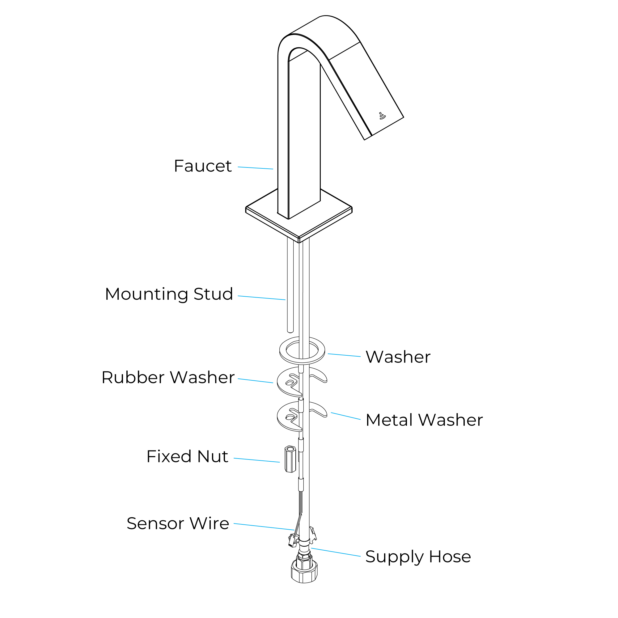
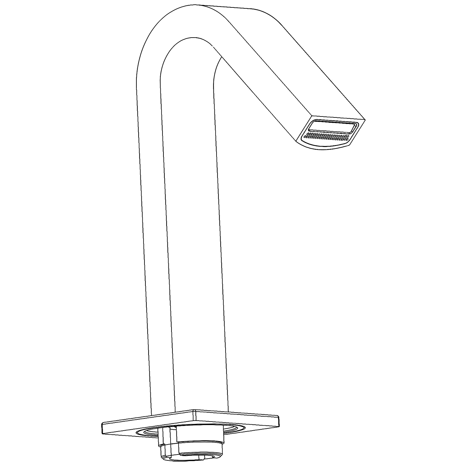
How to Install the Faucet
1. Fixing the faucet and lavatory
Install the mounting stud to the bottom of the faucet, then slip the washer over the mounting stud and put them into the groove on the spout. Insert the power wire and supply hose into the hole from the underside of the lavatory. From the underside of the lavatory, slide the rubber washer, metal washer and
fixed nut onto the mounting stud. Tighten nut to make faucet installed on the lavatory.
|
|
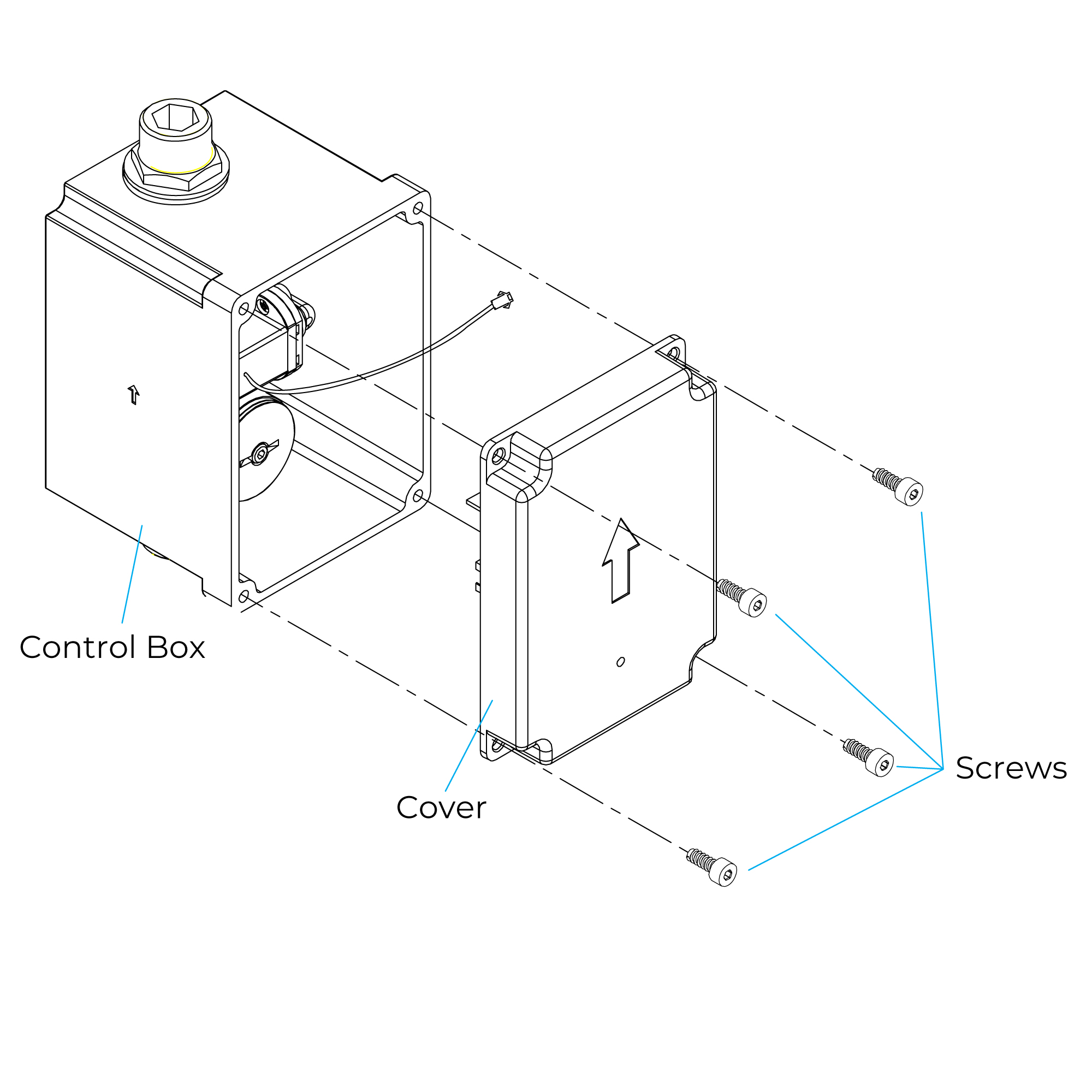
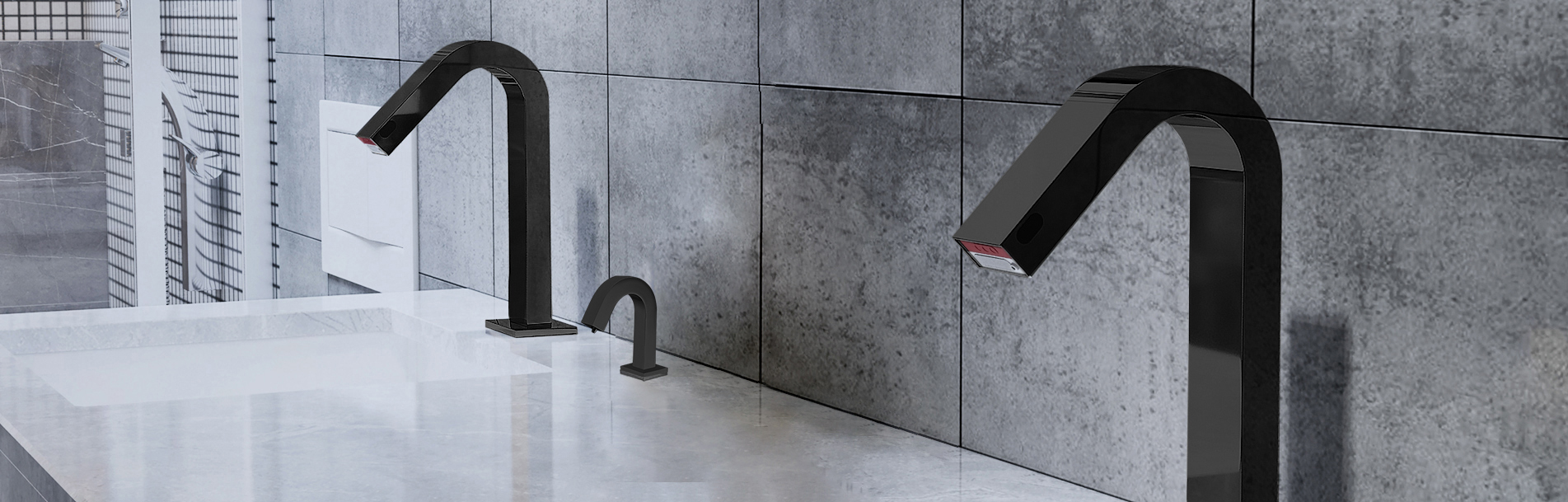
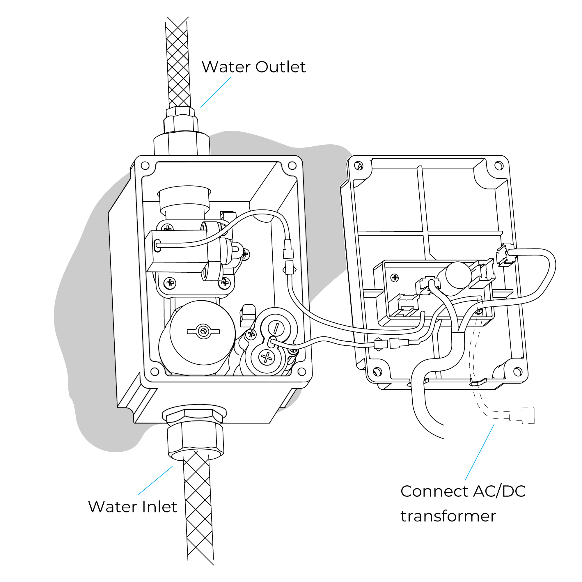
2. Fix the control box
Remove the cover after loose the screws. Determine the installation location of control box per rough-in, then drill holes and place sheath in it. Make the control box cling on the wall and outlet upturned, then fix the control box on the wall by screws, keep the control box parallel to the wall.
|
|
|
|
|
Step 3:
|
|
Step 4:
|
|
|

|
|
|
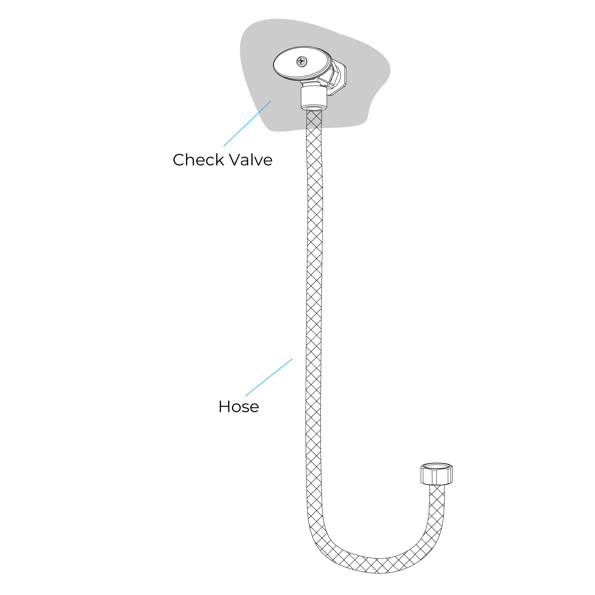
Connect the check valve and outlet together, then connect the hose and check valve. Put a bucket in the front of the hose, turn on the check valve completely and open the water supply. After the water flushing about 1 minute, make sure no leakage and turn off the water supply.
|
|
|
|
|
Step 5:
|
|
Step 6:
|

|
|

|
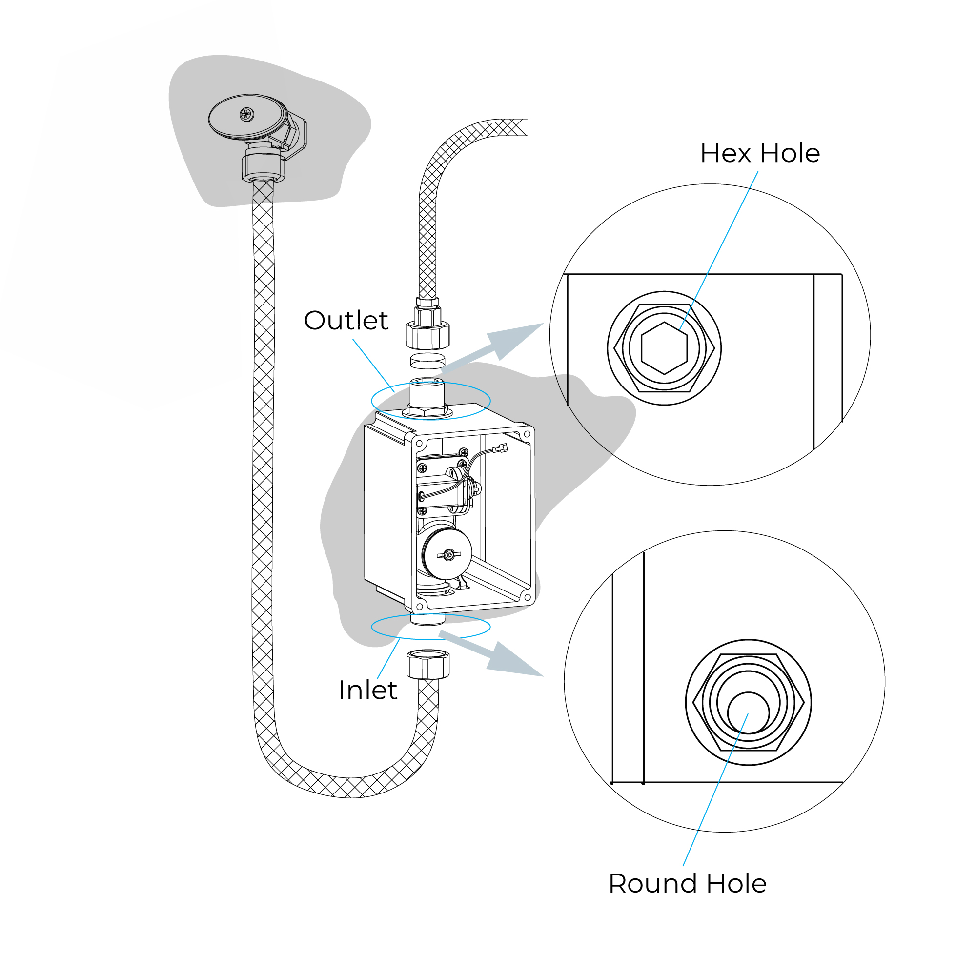
Connect a hose to the inlet of valve, then connect the outlet of valve and inlet of spout assy.
Note:
1. Do not lose the washer of the hose.
2. Please let users prepare the check valve by themselves.
3. Do not confuse the inlet and outlet.
|
|
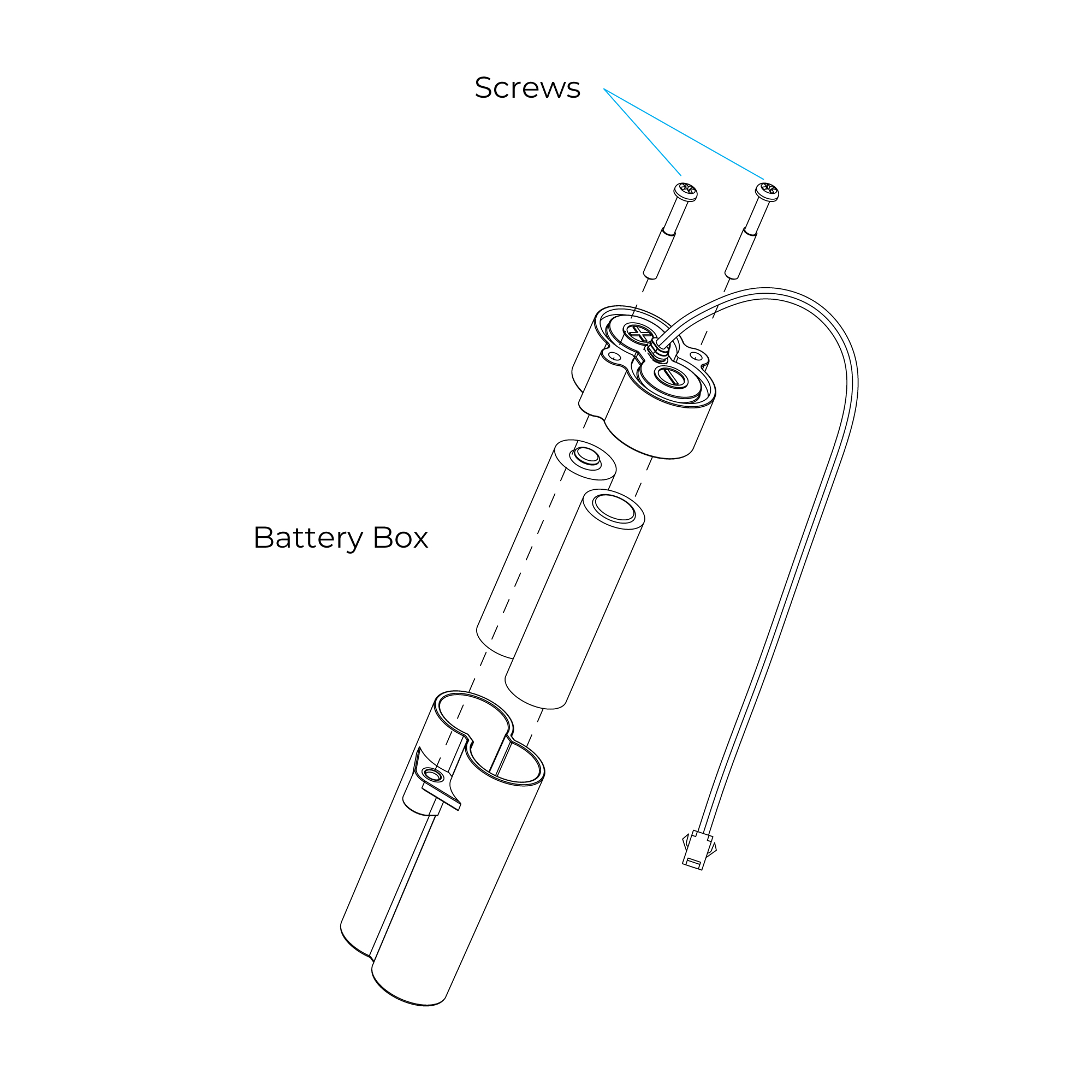
Take out the battery box and loose the screws, place two “AA” batteries into the box according to the negative and positive pole mark on the cover of the battery box. Put the box in the particular groove in the valve box after tight the screws.
Note:
Do not mistake the pole and mixture the new and used batteries.
|
|
|
|
|
Step 7:
|
|
Step 8:
|
|
|
|
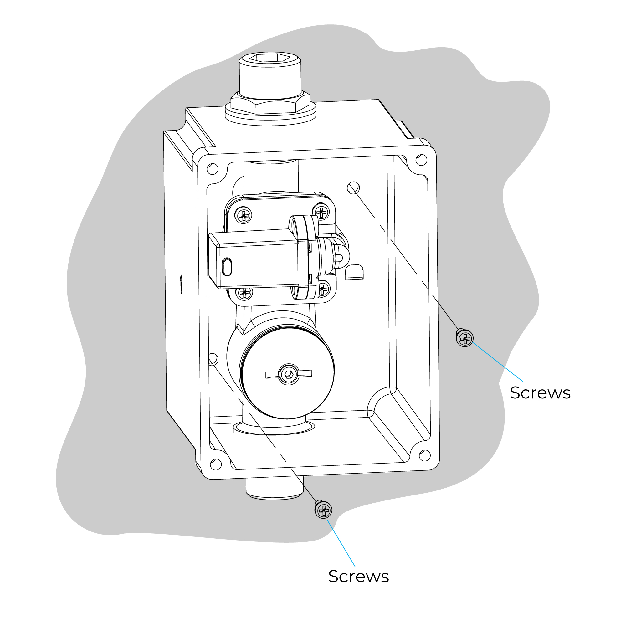
Finally, connect the red-green lines in solenoid valve and the cover of valve box, then connect the black-orange lines in power supply and control board (If your faucet is AC version, please let the black-green line in the control board through the “U” gap and connect with the line of AC power box). Connect the red and white connectors in the sensor line and cover, and tight the box and cover by screws.
|
|
Note:
1. When installing the box and cover by screws, make sure the sensor line needs to be through the “U” Gap of cover.
2. Connect the batteries, the faucet will be in the period of automatic adjusting sensing distance (about 2minutes). The faucet will not work during this period.
|
|
|
|
|
Step 9: (Sensing Range)
|
|
Step 10:
|

|
|
|
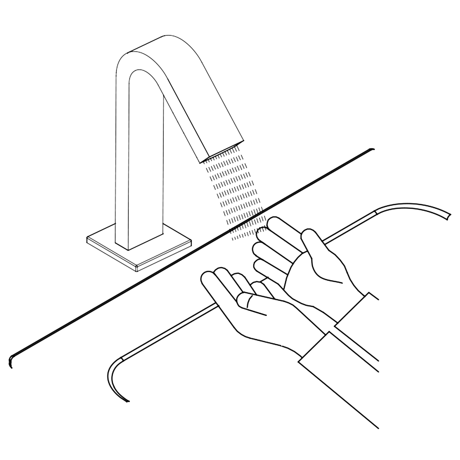
Put your hand in the sensing -range, the faucet should turn on. The faucet should turn off after removal within 0.5~1 seconds. The sensing distance will be adjusted automatically as per the condition of the lavatory and the surrounding environment.
|
|
|
|
|
|
|
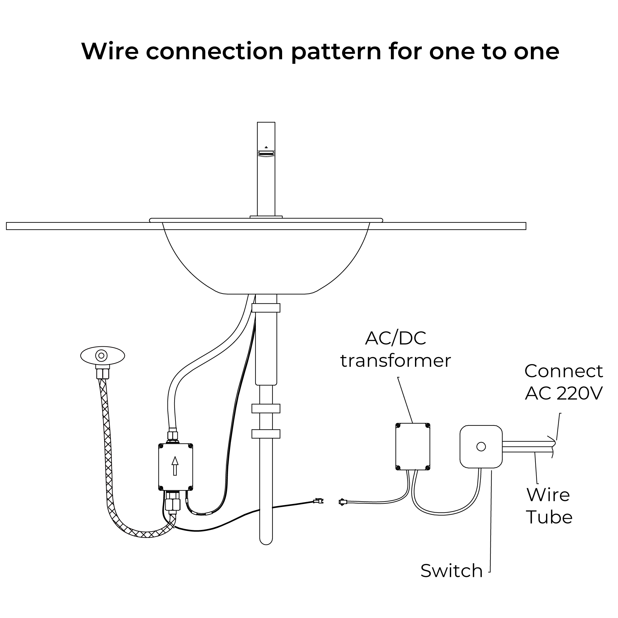
Step 11: (Single Faucet Connection)
|
|
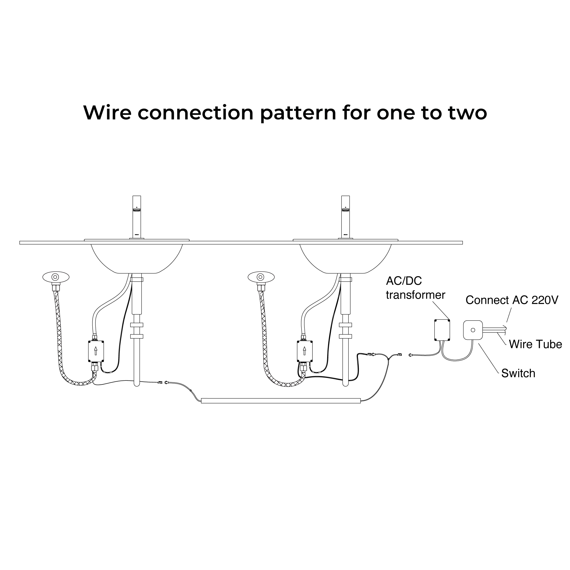
Step 12: (Multiple Faucet Connection)
|
|
|

|
|
|
|
|
|
|
|
|
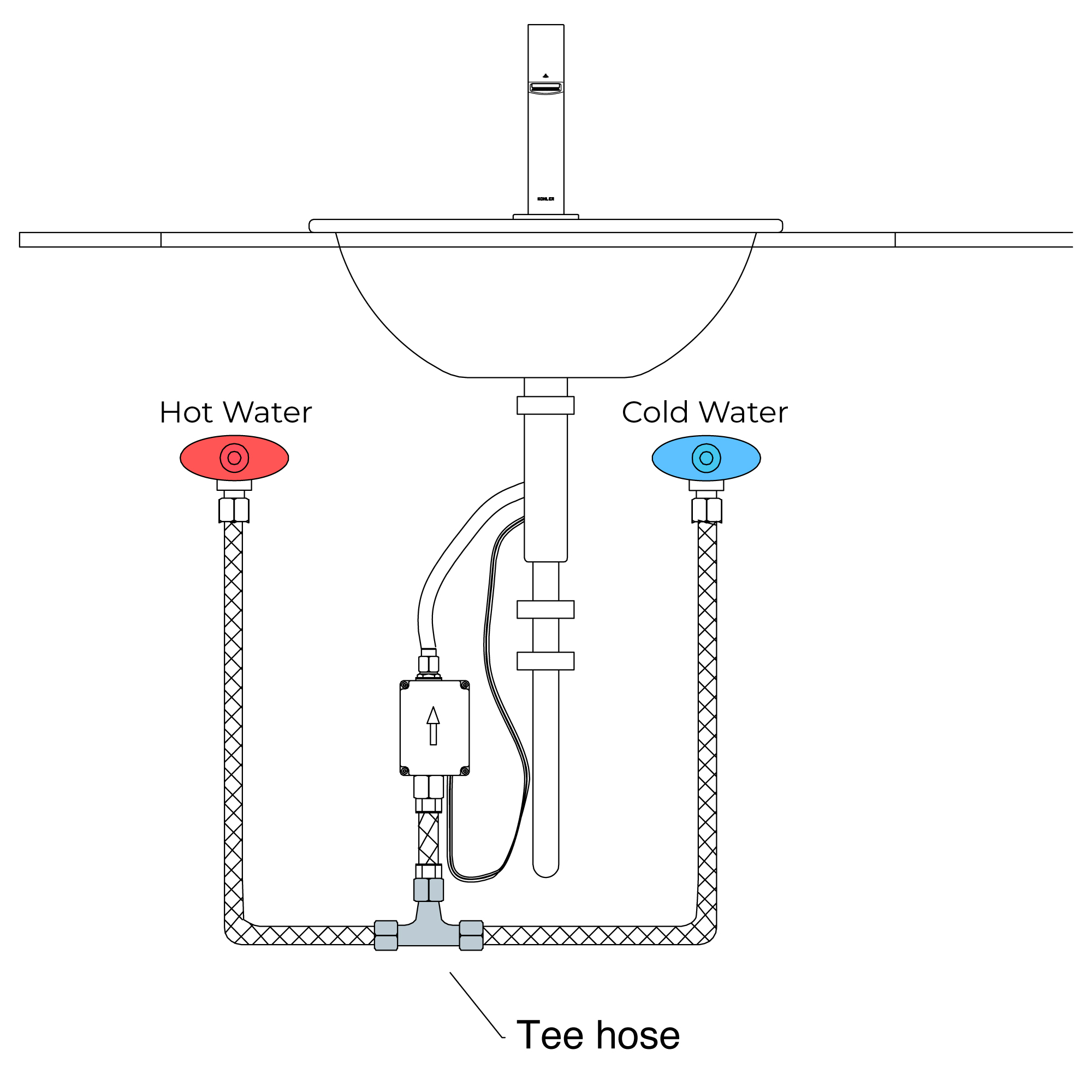
Step 13: (Hot & Cold Connection)
|
|
|
|
|
|
|
|
|
|
|
|
|
|
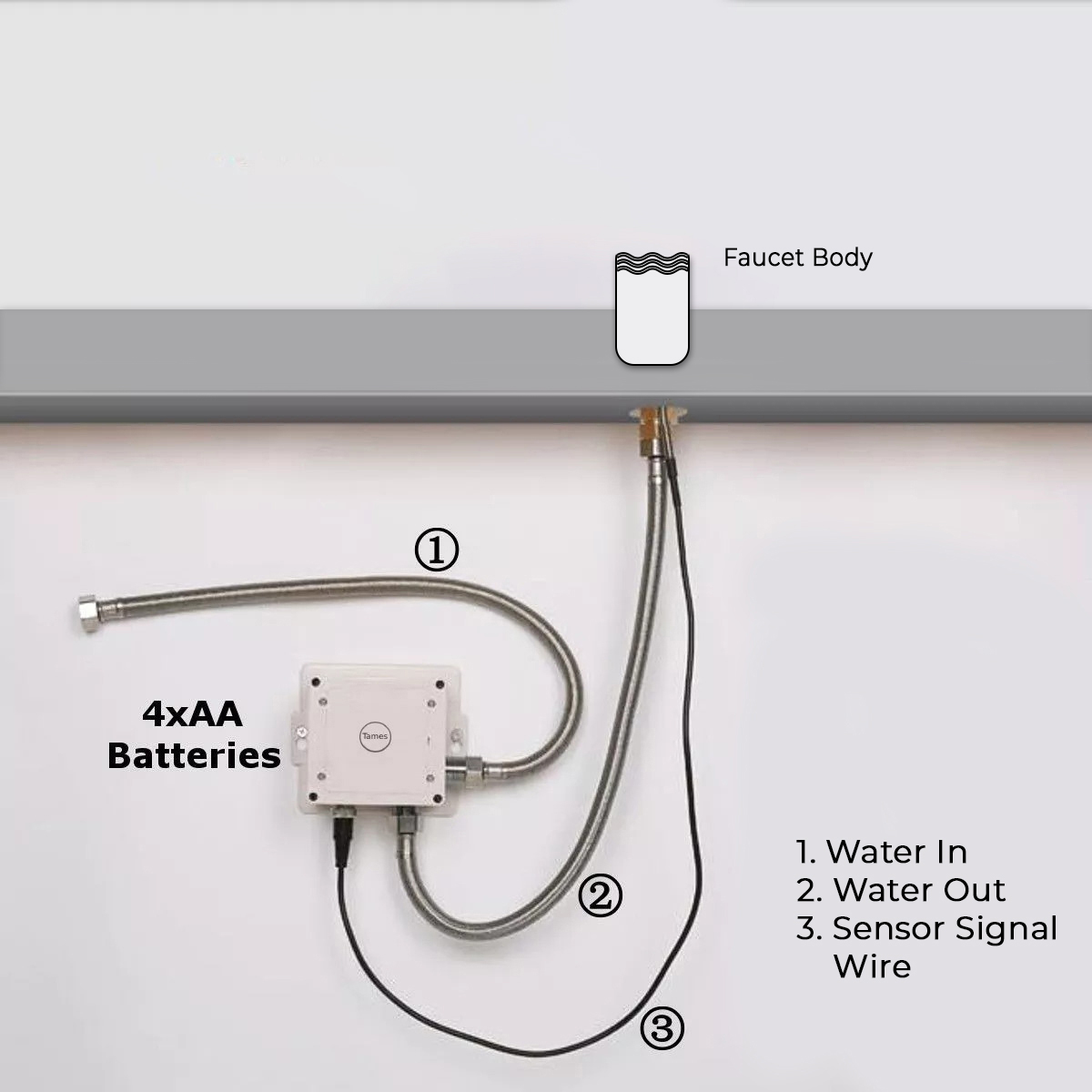
Battery (DC 6V) Only Control Box
|
|
|
|
Normal Water Connection
|
|
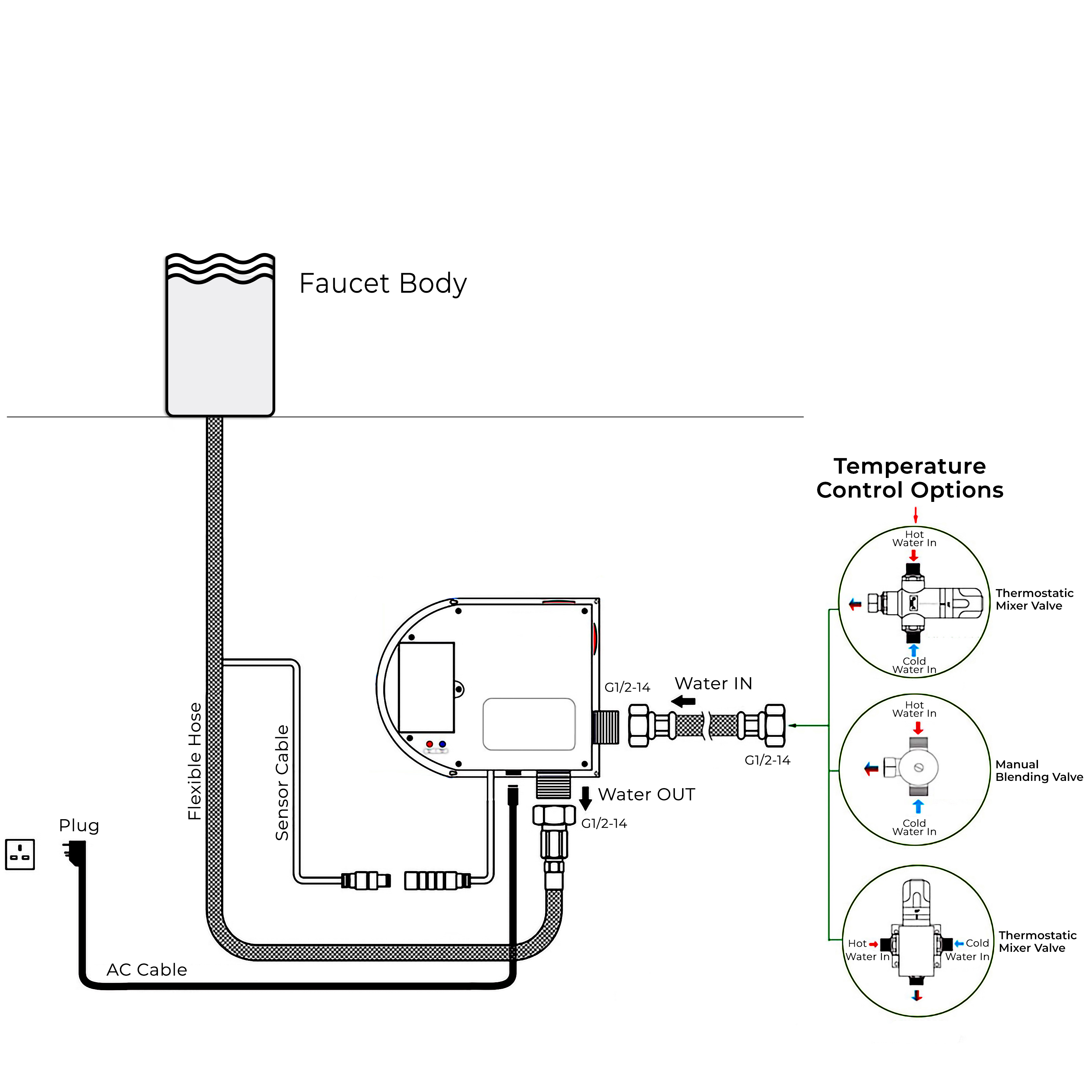
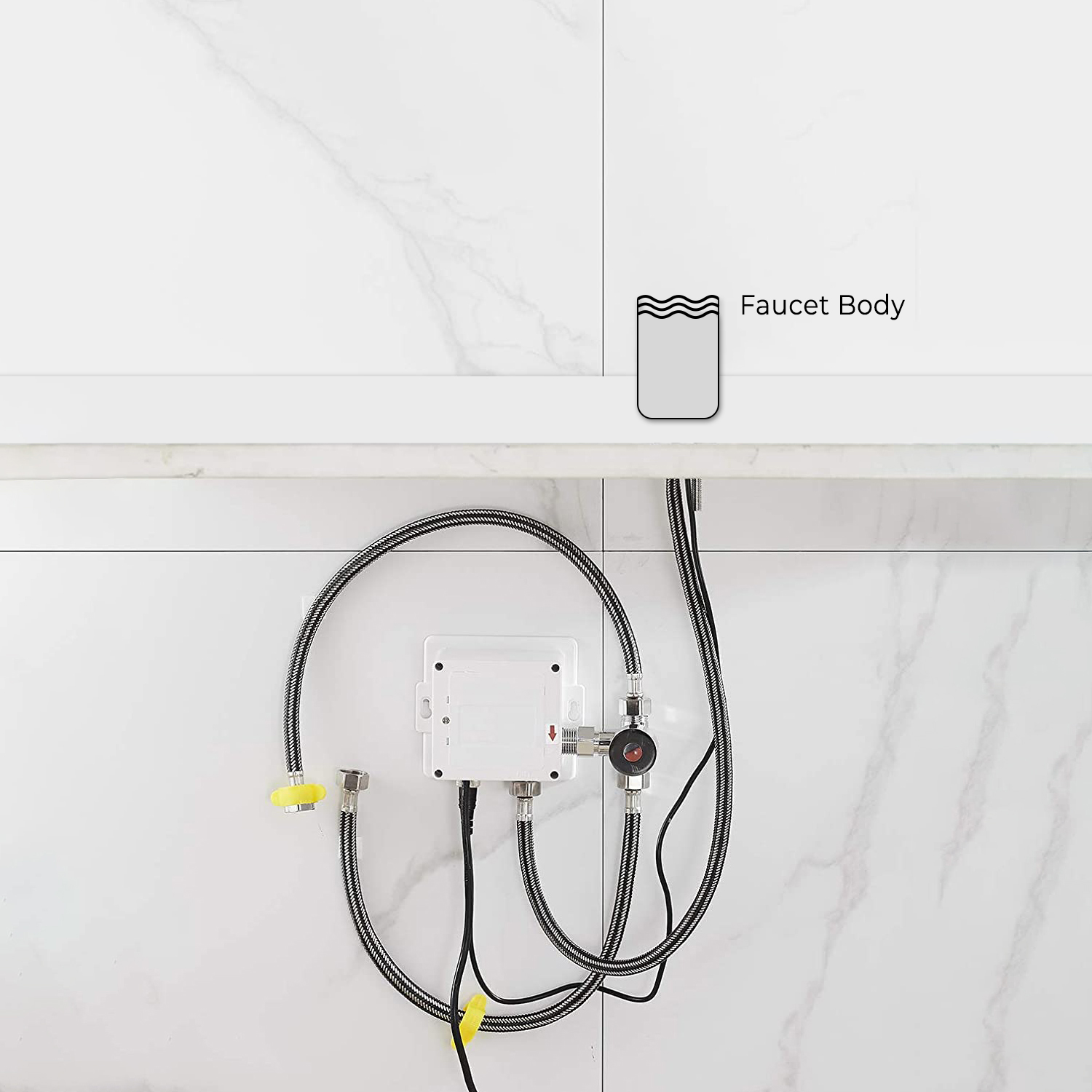
(Hot & Cold Water Connection)
|
|
sensor
|

|
|
|
|
|
Battery (DC 6V) & AC 220V Control Box
|
|
|
|
|
|
|
|
|
|
|
|
|
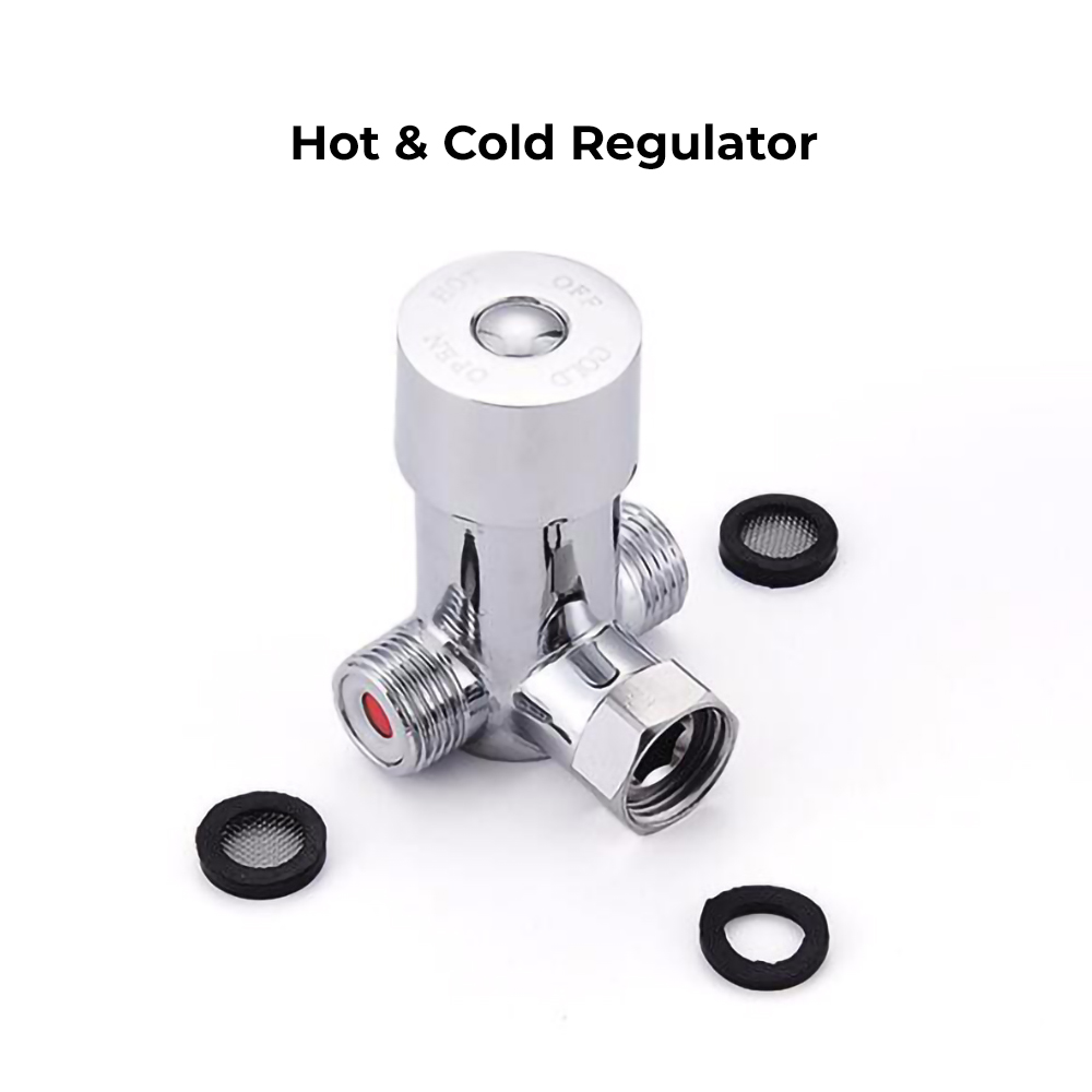
Hot & Cold Regulator
|
|
Step 6: (Correct way for Hose)
|
|
|

|
|
|
|
|
|
|
1. Note of the Indicator Flashing
The indicator is the only and effective way to learn the faucet's working conditions. So the users can use the sensor faucet correctly with knowing the meaning of the sensor indicator's flashing.
(1) Fast flashing means the faucet is in the period of adjusting sensing distance after power on for 2 minutes. During these 2 minutes, please do not put objects in the sensing range.
(2) The indicator flashes every 2 seconds: As for DC type faucets, the symptom indicates that the unit is out of battery and ceases working. Recommend to replace batteries. As for AC type faucets, there're two possibilities. One possibility is that the unit is out of battery while the other is that bad wire connection occurs to DC terminal of the power box provided AC supply functions normally.
(3) In normal conditions, the water will flow and the indicator will flash one time when objects are inducted. (The indicator does not flash when faucet stops flowing.)
2. Overtime Flowing Control
When the faucet works for about 1 minute continuously, the water will be shut off automatically. After that, objects must be removed from the sensing range. Then the water will flow when objects go into the sensing range again. Otherwise, the faucet will not work.
3. Intelligent Stopping Flowing
Water will flow out when objects are put into the sensing range. If the objects hold still for 15 seconds, the faucet will shut off automatically. After that, objects must be removed from the sensing range. Then the water will flow when objects go into the sensing range again. Otherwise, the faucet will not work.
4. Clean the Filtration System
The faucet includes a connector assembly with a high-quality filtration system. If there is a lot of debris in the supply pipes or the quality of water is bad, it will cause the flow in bad condition. Please clean the filtration system as the following steps:
(1) Turn clockwise the adjustment bolts on the connector assemblies with the hex wrench, in order to close the connector assemblies;
(2) Screw off the connector caps counterclockwise with the special key;
(3) Remove and clean the filters, then reinstall them;
(4) Tighten the connector caps clockwise with the special key. Turn counterclockwise the adjustment bolts on connector assemblies with the hex wrench.
If necessary, then reinstall it to improve the flow condition.
Note: the strainer must be fit back to the spout after it is cleaned.
|
|

|
Flexible Connecting Hose
Care must be taken when connecting the flexible connection hose from the power supply box to the spout to ensure it does not bend sharply and kink or twist.
See above for recommended ways to fit the flexible connecting hose.
Important: Failure to follow these guidelines may result in poor performance and damage to the flexible connection hose.
|
|
|
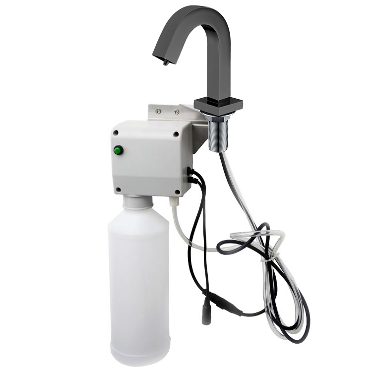
Automatic Soap Dispenser Installation Instructions
|
Step 1:
|
sensor
|
Step 2:
|
|

|
|
|
|
|
|
Max Deck Thickness - 1.5"
|
|
|
Step 3:
|
|
Step 4:
|
|
|
|

|
|
|
|
|
|
|
Step 5:
|
|
Step 6:
|
|
|
|
|
|
|
|
|
|
|
Step 7:
|
|
Step 8:
|
|
|
|
|
|
|
Step 9:
|
|
Step 10:
|
|

|
|
|
|
|
|
|
|
|
|
|
|
|
|
Features:
More Hygienic
The proximity sensor removes the need to touch the spout, reducing the spread of germs and reducing the chance of cross-infection.
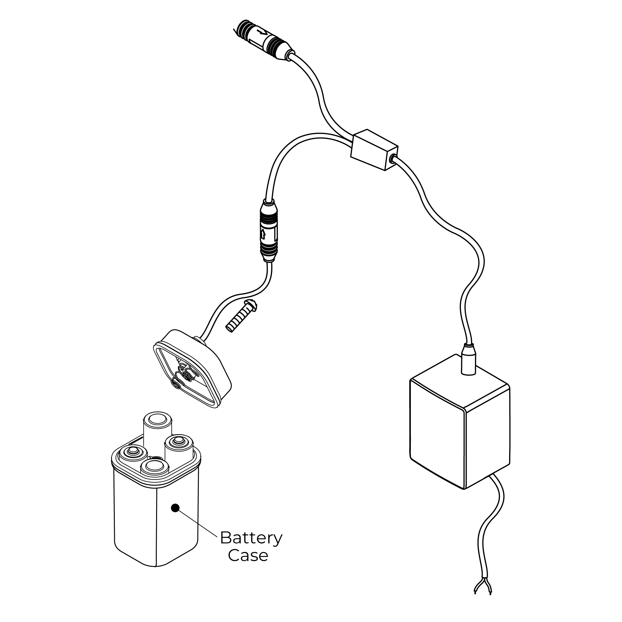
Battery Override
Your infrared soap dispenser is supplied with a backup battery pack. In the event of a power failure, the product will automatically switch to battery-operated mode to ensure the spout continues to function.
Low Battery Warning
When the batteries run low and the power falls below 3.9V the sensor light will flicker to indicate the batteries are running low and need replacing.
When the batteries are exhausted the sensor light will not light up.
Electrical Connections
Regulations: The electrical installation must be carried out in accordance with the national electrical regulations and installed by a qualified person.
Safety: In the interests of electrical safety a 30 mA residual current device (R.C.D not supplied) should be installed in the supply circuit. This may be part of a consumer unit or a separate unit.
Before starting work on the electrical supply ensure the power supply is isolated.
DO NOT allow the supply cord to contact hot surfaces. The cord should be safely routed and secured by cable clips.
Connections: The power supply must be permanently connected to the fixed wiring of the mains supply using the factory fitted supply cord, via a switched fused spur off the ring main.
The wires in the mains lead are coloured in accordance with the following code:
Blue: Neutral
Brown: Live
As the colours of the wires in the mains lead of this appliance may not correspond with the coloured markings identifying the terminals in your connection unit proceed as follows;-
The wire which is coloured blue must be connected to the terminal which is marked with the letter ‘N’ or is coloured black.
The wire which is coloured brown must be connected to the terminal which is marked with the letter ‘L’ or is coloured red.
Installation
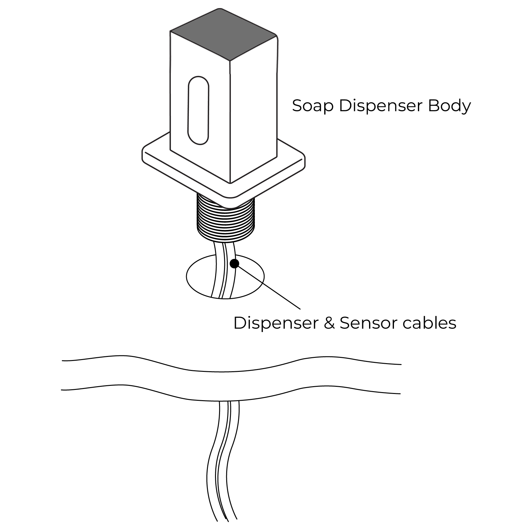
1. Fit The Spout
Fit the spout to the sink/basin ensuring the dispensing cable and sensor cable are threaded through the hole in the sink/basin.
2. Secure Spout to Sink / Basin
Screw the metal back nut onto the thread of the spout upto the underside of the sink/basin.
Tighten backnut using a suitable spanner.
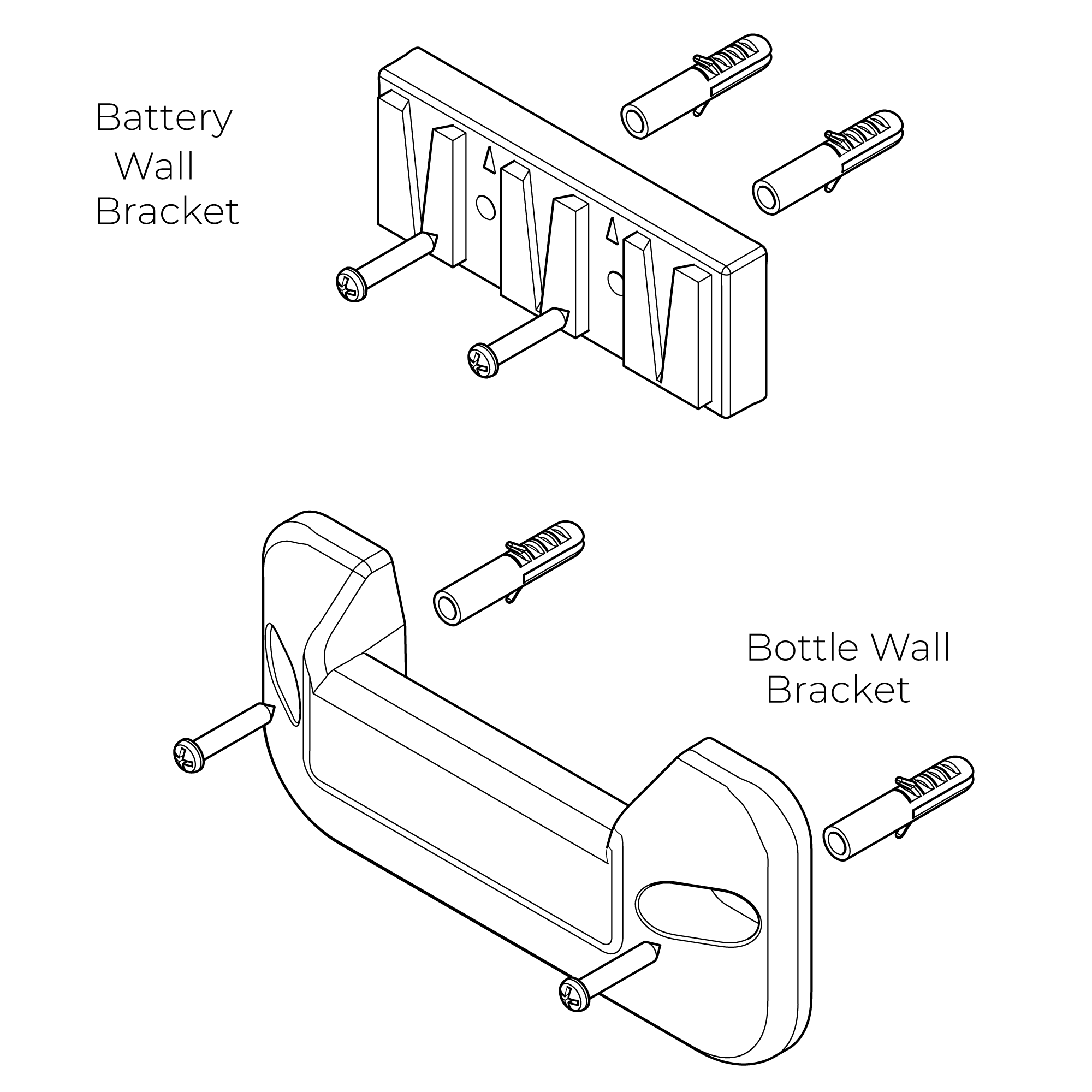
3. Fit Wall Brackets
Position the brackets onto the wall surface and mark the position of the fixing holes.
Remove the brackets and drill suitable holes for the wall plugs supplied.
Before drilling into walls, check that there are no hidden electrical wires, cables or water supply pipes. This can be checked with the aid of an electrical detector:
If power tools are used do not forget to:
- Wear eye protection
- Unplug equipment after use
Fit the wall plugs and position the brackets into position and secure using the screws provided.
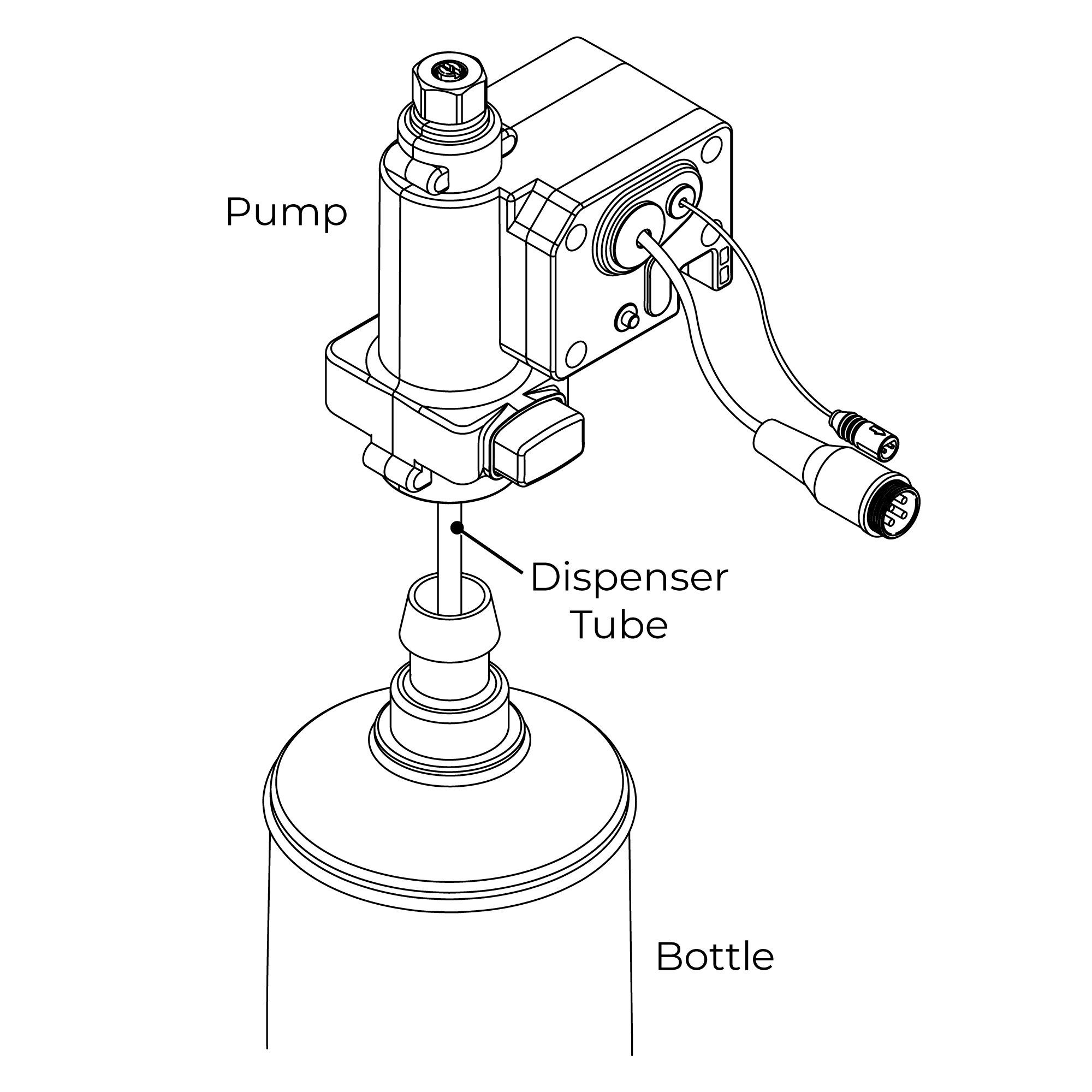
4. Attach Pump to Bottle
Ensure the dispenser tube is located inside the bottle and push the pump down firmly onto the bottle until a loud ‘click’ is heard.
To remove the pump from the bottle press the release button in on the side of the pump and pull the pump from the bottle.
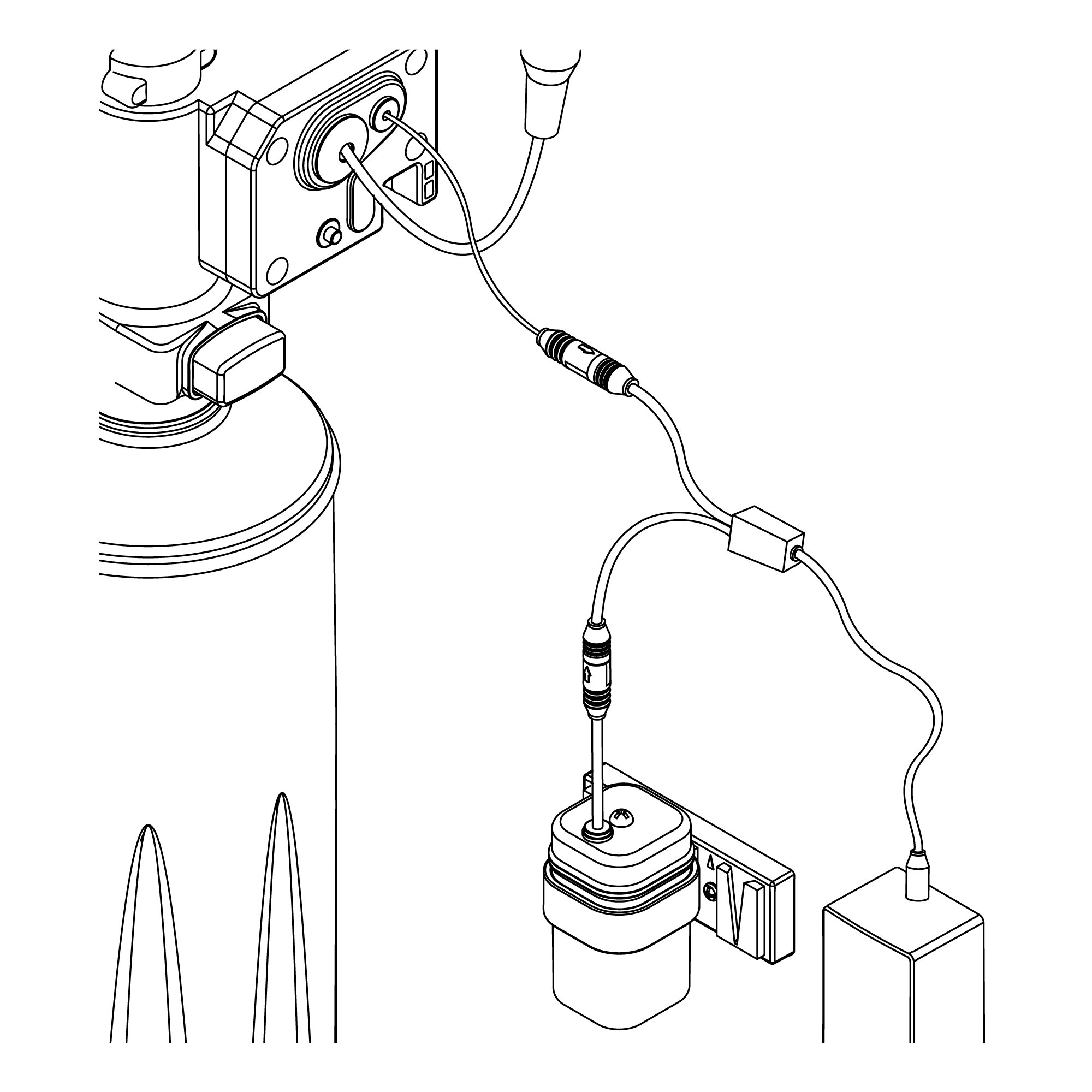
5. Connect Sensor Cable and Dispenser Cable
Connect the sensor cable from the spout to the sensor cable on the pump. Push the two connections together and tighten the connecting ring to ensure the two connections are locked together.
Connect the dispensing cable from the spout into the top connection on the pump.
Push the threaded connection of the dispensing cable into the connection on the pump and tighten the nut ensuring it is fully tightened.
A suitable spanner may be used to tighten the nut.
6. Place Pump into Bracket
The pump has a cut-out section which the wall bracket slots into.
7. Connect Power Supply Cable
Before starting any electrical work ensure the power supply is isolated.
Wire the electrical power cable into a switched fused spur off the ring main.
The blue wire should be wired to the neutral connection and the brown wire should be connected to the live connection.
Important: The power lead must be permanently connected to the fixed wiring of the mains supply using the factory supplied power cable.
Plug the power cable into the power cable on the pump.
8. Inser |
|
|