


FontanaShowers® | Architectural and Installation Resource
Fontana DualOrion™ Gold Widespread Basin Faucet: Below-Deck Installation View
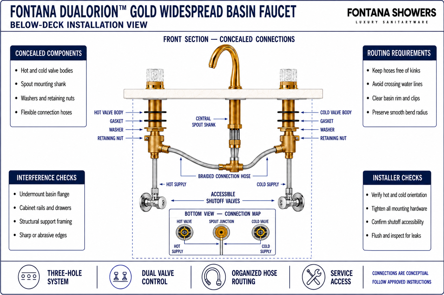
This below-deck coordination resource helps designers, fabricators and installers understand the concealed arrangement beneath the spout and crystal handles. It identifies valve bodies, threaded shanks, gaskets, washers, retaining nuts, flexible connections, hot and cold supplies and required service access so the three-hole assembly can be installed and maintained without interference.

The Installation Continues Below the Counter
The exposed spout and two crystal handles are only the visible part of the installation. Below the deck, each component requires secure mounting hardware and an unobstructed connection path. The concealed arrangement must also remain accessible for tightening, supply isolation, inspection, hose replacement and future valve service.
- Spout assembly: Shank, washer, retaining nut and outlet connections
- Hot valve: Mounting body, supply inlet and connection to spout
- Cold valve: Matching body, inlet and connecting hose
- Deck hardware: Gaskets, washers and securing nuts
- Water routes: Hot, cold and mixed-water connection paths
- Isolation points: Accessible hot and cold shutoff valves
- Service zone: Clear space for tools, inspection and replacement
Below-Deck Installation Arrangement
The enlarged section shows the concealed relationship among the two handle valve bodies, central spout shank, securing hardware and flexible water connections. The diagram establishes routing and access relationships without assigning unpublished connection sizes or installer-specific hose lengths.
Conceptual below-deck view. Confirm the supplied component arrangement, connection method and service access before final tightening.
| Coordination item | Required review | What it controls | Verification |
|---|---|---|---|
| Spout mounting shank | Confirm washer, retaining nut and connection access | Central fixture support and mixed-water delivery | Dry-fit inspection |
| Hot valve assembly | Identify inlet, mounting body and spout connection | Hot-water control and secure handle mounting | Installer connection check |
| Cold valve assembly | Identify inlet, mounting body and spout connection | Cold-water control and balanced hose routing | Installer connection check |
| Flexible connections | Route with relaxed bends and no twisting or pinching | Reliable flow and reduced stress at fittings | Visual routing inspection |
| Isolation and service zone | Preserve access to shutoffs, nuts and connections | Commissioning, inspection and future maintenance | Tool-access demonstration |
Below-Deck Installation Process
Map the Concealed Zone
Mark the basin underside, mounting clips, cabinet rails, drawers and partitions around all three holes.
Dry-Fit the Valve Bodies
Position the hot and cold assemblies beneath their crystal handles and confirm unobstructed mounting.
Secure the Central Spout
Install the specified gasket, washer and retaining nut while preserving access to the outlet connections.
Connect Both Valve Outlets
Route the hot and cold valve connections toward the spout without crossing, twisting or sharp bending.
Connect the Water Supplies
Connect each valve inlet to the correct accessible isolation valve using the specified connection method.
Check Hose Routing
Keep flexible lines clear of the basin, clips, drawer movement, sharp edges and cabinet hardware.
Test Service Access
Confirm that tools can reach every mounting nut, fitting and shutoff after the basin is installed.
Flush, Test and Inspect
Flush the lines, pressurize the system and inspect all concealed joints before closing the cabinet.
Below-Deck Planning Considerations
Correct Valve Orientation
Keep hot and cold valve bodies correctly identified and aligned beneath their respective controls.
Independent Mounting Access
Provide room to tighten each of the three fixture components without removing adjacent hardware.
Relaxed Hose Routing
Form smooth curves that avoid kinks, tension, abrasion and contact with sharp cabinet edges.
Accessible Isolation Valves
Locate hot and cold shutoffs where they can be reached without dismantling the basin or cabinetry.
Basin and Cabinet Separation
Keep valve bodies, nuts and hoses clear of basin flanges, clips, drawer rails and partitions.
Future Maintenance
Preserve visible and physical access to concealed joints so routine service remains practical.
Below-Deck Installation Checklist
- The hot and cold valve bodies are positioned beneath the correct crystal handles.
- All three assemblies use their specified gaskets, washers and retaining hardware.
- The central spout connections remain accessible after the mounting nut is tightened.
- Flexible connections follow smooth routes without tension, crossing or sharp bends.
- The hidden basin rim and mounting clips do not contact valve bodies or hoses.
- Drawer rails, cabinet partitions and stored items remain outside the service zone.
- Hot and cold isolation valves are clearly identified and readily accessible.
- Every concealed joint has been flushed, pressure-tested and inspected for leakage.
Related Product and Planning Resources
Project verification: This page identifies below-deck installation relationships but does not replace the approved product submittal or installation instructions. The designer, fabricator and licensed installer must verify the supplied components, connection arrangement, basin and cabinet conditions, isolation valves and service access before final installation.









