


FontanaShowers® | Architectural and Installation Resource
Fontana DualOrion™ Gold Widespread Basin Faucet: Minimum Counter Clearance
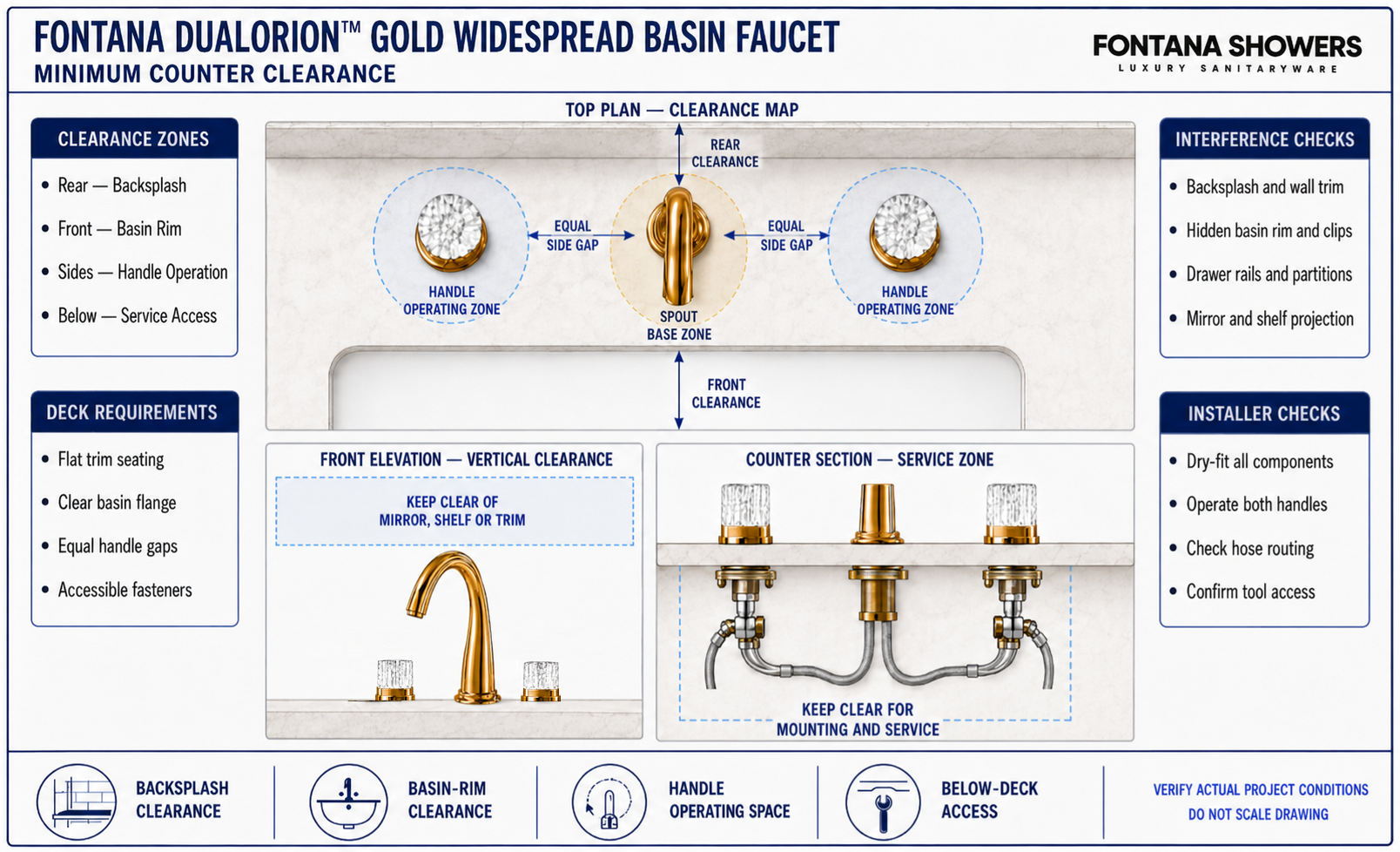
This clearance-planning resource helps designers, fabricators and installers reserve practical space around and beneath the faucet. It addresses the backsplash, basin rim, crystal-handle operating zones, escutcheon footprints, mounting hardware and concealed connections so the fixture can be installed, operated, cleaned and serviced without interference.
Clearance Is More Than a Single Measurement
A workable installation requires clear space in several directions. The spout base must sit fully on a flat deck, each crystal handle must remain comfortable to operate, the basin rim must not obstruct mounting hardware, and the area beneath the countertop must accommodate valve bodies, fasteners, supply lines and future service tools.
- Rear zone: Faucet and handle clearance from backsplash
- Front zone: Clearance from basin rim and cutout
- Side zones: Free operation around crystal handles
- Base zones: Flat escutcheon seating surfaces
- Lower zone: Valve, hose and mounting access
- Vertical zone: Mirror, shelf and wall-trim clearance
- Cleaning zone: Reachable surfaces around all components
Counter Clearance Zones
The top plan identifies the usable deck area that must remain free around the three components. The section view shows the concealed space needed below the counter. Because the approved minimum has not been supplied, the diagrams identify clearance relationships rather than publishing an estimated numerical requirement.
Conceptual clearance map. Confirm final space requirements by dry-fitting the supplied components with the selected basin and vanity.
| Clearance zone | Area affected | What must remain possible | Typical conflict |
|---|---|---|---|
| Rear | Between faucet components and backsplash | Handle operation, cleaning and trim seating | Raised splash, wall trim or mirror projection |
| Front | Between components and basin rim | Secure mounting and water delivery into bowl | Hidden basin flange or cutout edge |
| Side | Between spout and both handles | Independent control operation and cleaning access | Unequal or excessively tight component gaps |
| Vertical | Above the high-arc spout | Installation, cleaning and visual separation | Mirror cabinet, shelf or projecting trim |
| Below deck | Under all three mounting positions | Fastener access, hose routing and valve service | Basin rim, drawers, rails or cabinet partitions |
Counter-Clearance Verification Process
Map the Basin Footprint
Mark the visible rim, hidden flange, mounting clips and underside bowl profile on the countertop plan.
Locate the Spout
Position the spout so its 5.91-inch reach clears the rear rim and projects into the usable basin interior.
Check the Backsplash
Confirm the spout base and both handles sit on flat deck surfaces without touching raised wall finishes.
Operate Both Handles
Dry-fit the crystal controls and verify full, comfortable use without contact with the spout or backsplash.
Review Vertical Space
Compare the 9.06-inch overall height with mirrors, shelves, cabinets and projecting trim.
Inspect Below Deck
Check valve bodies, fasteners and hoses against the basin, framing, drawers and cabinet walls.
Test Service Access
Confirm an installer can reach mounting nuts, supply connections and shutoff valves with appropriate tools.
Approve Before Drilling
Record the verified layout only after the complete three-piece fixture has been dry-fitted successfully.
Clearance Planning Considerations
Flat Trim Seating
Every escutcheon must rest completely on a level surface without crossing seams, bevels or curved transitions.
Equal Handle Gaps
Maintain matching clear spaces between each crystal handle and the central spout for operation and symmetry.
Basin-Rim Separation
Keep openings and mounting hardware clear of the visible rim, hidden flange and attachment clips.
Backsplash Access
Provide enough room behind the fixture to clean surfaces and avoid trapping moisture around the bases.
Hose Bend Radius
Route flexible connections with relaxed curves and without pinching them between the bowl and cabinet.
Future Maintenance
Preserve access to valves and mounting hardware so service does not require removing the countertop.
Minimum-Clearance Checklist
- All three trim bases rest fully on flat, uninterrupted countertop surfaces.
- The spout clears the backsplash and directs water into the basin interior.
- Both crystal handles operate freely and have equal visible gaps from the spout.
- The hidden basin rim and clips do not obstruct any mounting position.
- The 9.06-inch arch clears mirrors, shelves and projecting wall details.
- Mounting nuts, valve bodies and supply lines remain accessible below the deck.
- Flexible connections follow smooth routes without tension or sharp bends.
- Cleaning and future maintenance can be performed without removing fixed finishes.
Related Product and Planning Resources
Project verification: This page identifies clearance relationships but does not establish a manufacturer-approved numerical minimum. The designer, fabricator and licensed installer must verify the physical fixture, basin, countertop, cabinetry and service access before drilling or final installation.









