


FontanaShowers® | Architectural and Installation Resource
Fontana DualOrion™ Gold Widespread Basin Faucet: Three-Hole Rough-In Drawing
This rough-in resource supports countertop fabricators, plumbing engineers, architects and installers planning the three separate deck openings required for the hot control, central spout and cold control. It explains centerline alignment, drilling sequence, below-deck coordination and pre-installation checks for a clean, symmetrical result.

Three Independent Deck-Mounted Components
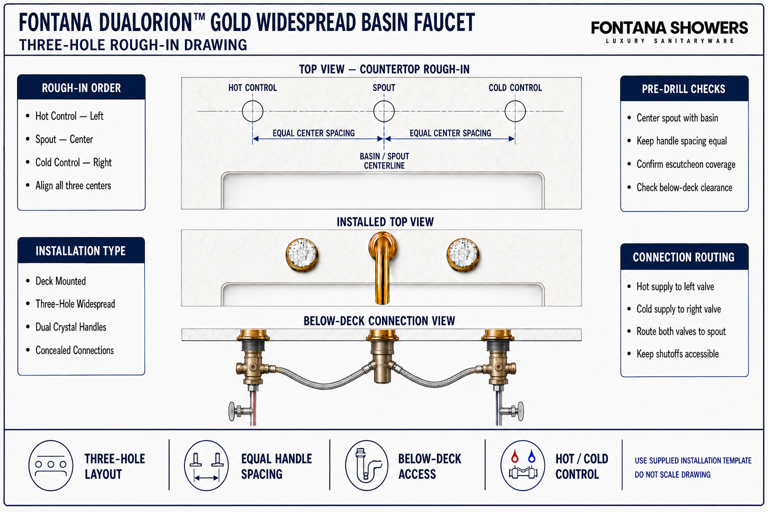
The faucet uses a dedicated opening for each crystal handle and a third opening for the high-arc spout. Correct rough-in begins with the basin and spout centerline; the two valve locations are then established symmetrically to produce balanced handle spacing and orderly concealed connections below the counter.
- Mounting: Deck mounted
- Layout: Three-hole widespread
- Left position: Hot-water control
- Center position: High-arc spout
- Right position: Cold-water control
- Controls: Two faceted crystal handles
- Connections: Concealed below the finished deck
Three-Hole Countertop Layout
The plan below establishes the correct order and alignment of the three mounting positions. The spout remains on the basin centerline, while both handles are placed at equal distances from the spout centerline. Opening sizes must be transferred from the supplied installation template or measured directly from the fixture’s mounting shanks before fabrication.
Conceptual rough-in arrangement—not a drilling template. Confirm every opening against the supplied hardware before cutting the finished deck.
| Position | Deck component | Below-deck requirement | Coordination purpose |
|---|---|---|---|
| Left | Hot crystal handle | Hot valve body and supply connection | Maintain equal spacing from the central spout. |
| Center | High-arc spout | Spout shank, mounting hardware and mixed-water connections | Align outlet with the usable basin area. |
| Right | Cold crystal handle | Cold valve body and supply connection | Mirror the hot-control position across the centerline. |
Recommended Rough-In Sequence
Confirm the Basin
Verify the selected lavatory, rim profile, backsplash and underside structure provide room for all three components.
Establish Centerline
Mark the basin centerline on the finished deck and use it as the center of the spout opening.
Set Handle Centers
Position hot and cold controls symmetrically on opposite sides of the spout using the approved template.
Check Below Deck
Confirm valve bodies, fasteners and flexible lines will clear the basin, framing, drawers and cabinet partitions.
Make Pilot Marks
Recheck orientation and equal spacing before making pilot marks or committing to full-size openings.
Drill and Protect
Use tooling appropriate for the countertop material, protect finished surfaces and deburr openings as required.
Dry-Fit Components
Test-fit the spout and both controls; confirm escutcheon coverage and handle clearance before connecting plumbing.
Connect and Test
Secure mounting hardware, route hot and cold connections, flush supplies and inspect every joint under pressure.
Countertop and Plumbing Coordination
Opening Verification
Match each opening to its actual threaded shank and confirm the escutcheon covers the finished cut completely.
Equal Handle Spacing
Keep both handle centerlines equally spaced from the spout centerline for a balanced front elevation.
Spout Alignment
Use the published 5.91-inch reach to ensure the outlet projects over the basin’s usable interior.
Backsplash Clearance
Check the 9.06-inch faucet height and allow room for operation, cleaning and nearby wall finishes.
Under-Counter Access
Keep mounting nuts, valve bodies and supply connections serviceable after the basin and cabinetry are installed.
Water-Line Routing
Avoid tight bends, abrasion points and interference between flexible connections, the basin and cabinet hardware.
Rough-In Verification Checklist
- The spout opening is centered with the basin and intended outlet location.
- The hot control is on the left and the cold control is on the right.
- Both handle centers are equally spaced from the spout centerline.
- All escutcheons will fully cover their respective finished openings.
- The deck is compatible with the supplied mounting hardware.
- Valve bodies and hoses clear the basin, drawers, shelves and structural supports.
- Hot and cold shutoff valves remain accessible after installation.
- The gold surfaces are protected throughout drilling and final assembly.
Related Product and Planning Resources
Project verification: This rough-in page is a coordination resource and does not replace the installation template, current manufacturer instructions or an approved project submittal. The countertop fabricator and licensed installer must verify opening diameters, center spacing, deck compatibility and connection clearances before fabrication.









