


FontanaShowers® | Architectural and Installation Resource
Fontana DualOrion™ Gold Widespread Basin Faucet: Valve and Cartridge Assembly
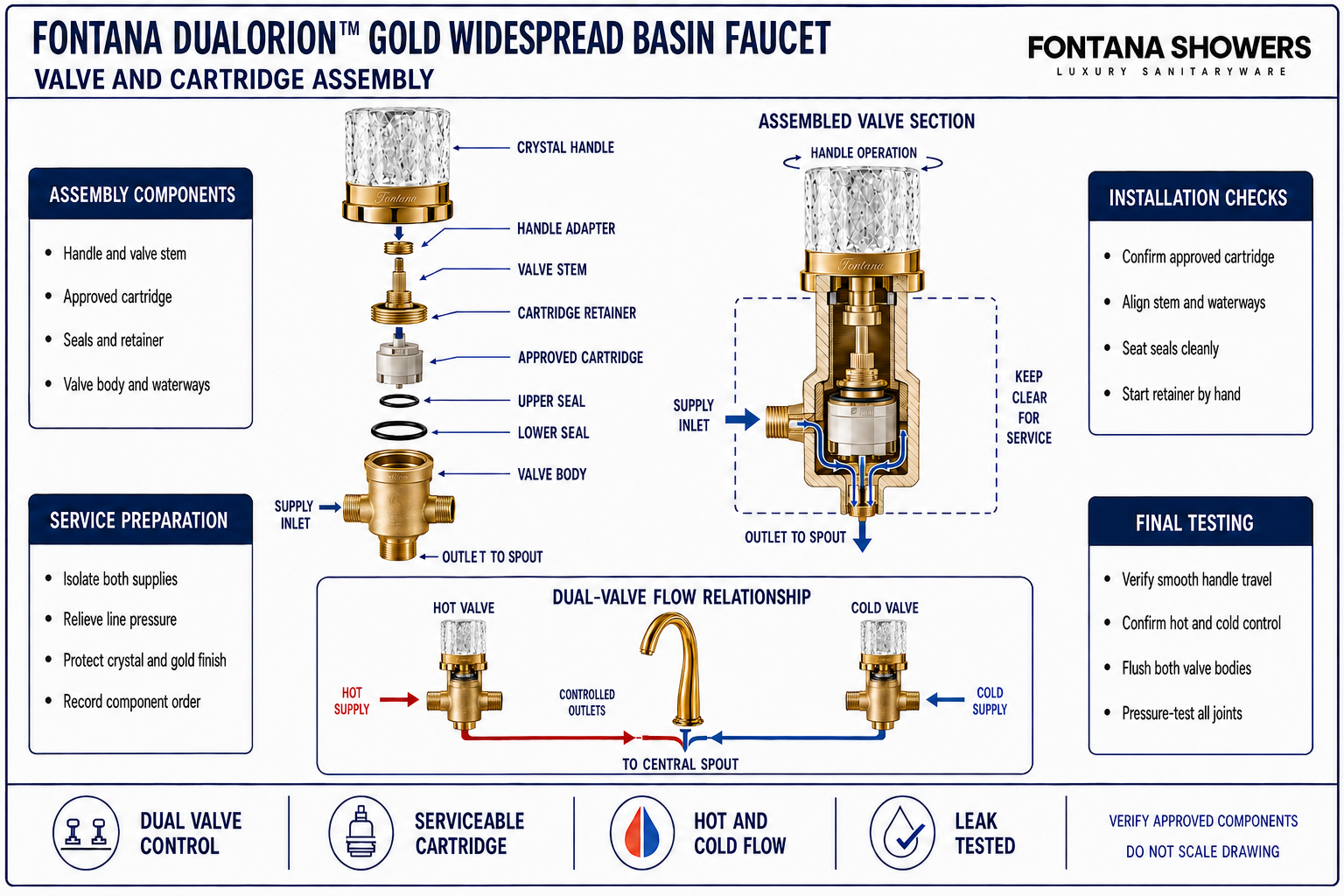
This installation and service-planning resource explains the relationship between each crystal handle, valve stem, cartridge, valve body, seals and concealed water connections. It addresses hot-and-cold orientation, cartridge seating, retaining components, flow direction, flushing, pressure testing and practical access for future inspection or cartridge replacement.

Each Handle Operates a Serviceable Valve Assembly
The hot and cold sides use separate handle-valve assemblies. Within each body, the cartridge and its seals regulate flow as the crystal handle turns the valve stem. Correct orientation, clean seating surfaces and approved retaining parts help prevent binding, crossed operation, internal leakage and difficult future service.
- Handle and stem: Positive engagement with smooth, controlled movement
- Cartridge: Correct approved component, orientation and full seating
- Sealing elements: Clean, undamaged and positioned in the approved order
- Retaining parts: Properly engaged without distortion or cross-threading
- Valve body: Stable, accessible and protected from installation debris
- Hot and cold: Correct side assignment and verified operating direction
- Connections: Inlet and outlet routes remain identifiable and serviceable
Valve Body and Cartridge Relationship
The enlarged section identifies the exposed handle, valve stem, cartridge, seals, retaining components and concealed valve body. The lower view traces building supply into each valve and the controlled outlet toward the central spout without assigning an unpublished cartridge type, thread standard, rotation angle or tightening value.
Conceptual valve-and-cartridge diagram. Confirm the approved cartridge, seals, component order, valve orientation and service procedure before installation or disassembly.
| Assembly item | Required review | What it protects | Field verification |
|---|---|---|---|
| Handle and valve stem | Confirm positive engagement and correct closed position | Smooth operation without slip, binding or overtravel | Functional movement check |
| Cartridge and seals | Use the approved cartridge and install on clean seating surfaces | Flow control and internal leak resistance | Part identification and seating inspection |
| Cartridge retainer | Engage evenly in the approved sequence | Cartridge stability without distortion or cross-threading | Thread and final seating check |
| Valve-body waterways | Keep inlet and outlet passages clear of debris | Correct supply-to-spout flow path | Flush and visual passage check |
| Hot/cold inlet and spout outlet | Connect to the correct ports with relaxed accessible routes | Correct temperature control and leak-free delivery | Pressure, function and access test |
Valve and Cartridge Assembly Process
Isolate and Relieve Pressure
Close both fixture supplies and operate the handles to confirm pressure has been safely relieved.
Protect and Remove the Handle
Protect the crystal and gold surfaces while removing the handle using the approved access method.
Expose the Cartridge Retainer
Remove the trim and retaining components in sequence, recording their order and orientation.
Inspect the Valve Interior
Check the cartridge, seals and valve-body seating surfaces for debris, wear or visible damage.
Seat the Approved Cartridge
Align the approved replacement or serviced cartridge and seat it fully without forcing the component.
Reinstall Retaining Components
Reassemble seals and retainers in the specified order, starting threaded parts by hand.
Restore the Handle Orientation
Reinstall the handle in its correct closed position and verify smooth travel before pressurizing.
Flush, Pressure-Test and Inspect
Restore water gradually, flush the assembly, test both sides and inspect all joints for leakage.
Valve and Cartridge Planning Considerations
Approved Cartridge Identity
Match any service component to current approved documentation rather than appearance alone.
Clean Seating Surfaces
Remove debris without scratching the valve body or leaving contamination beneath the seals.
Correct Orientation
Align cartridge features, valve waterways and stem position exactly as approved for each side.
Seal Condition
Replace damaged, displaced or contaminated sealing elements only with approved components.
Controlled Tightening
Start retaining parts by hand and follow approved tightening guidance to avoid distortion.
Future Service Access
Keep both valve bodies, connections and shutoffs reachable without disturbing the countertop.
Valve and Cartridge Assembly Checklist
- Hot and cold supplies are isolated and residual pressure is relieved before opening either valve.
- The cartridge has been positively identified as approved for the corresponding valve assembly.
- Valve-body seating surfaces and internal passages are clean and free of installation debris.
- All seals are undamaged, correctly oriented and installed in the approved sequence.
- The cartridge seats fully and the retainer starts freely without cross-threading or forcing.
- The handle returns to the correct closed position and operates smoothly through its intended travel.
- Hot/cold inlets and controlled outlets remain correctly connected and accessible.
- The completed assemblies have been flushed, pressure-tested and inspected for internal or external leakage.
Related Product and Planning Resources
Project verification: This page describes valve-and-cartridge assembly relationships but does not replace the approved product submittal or service instructions. The plumbing engineer, licensed installer and maintenance provider must verify cartridge compatibility, seal condition, component orientation, tightening requirements, flushing, connection access and leak-free operation.









