Fontana Touchless Fixtures™ | Architectural and Engineering Resource
Fontana Countertop Faucet & Soap Dispenser:
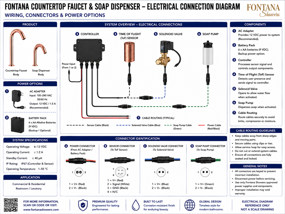
Time-of-Flight Sensor Electrical Connection Diagram
This electrical connection resource is intended to support architects,
electrical designers, plumbing engineers, contractors, installers,
commissioning personnel and facility managers coordinating the Fontana
countertop faucet and automatic soap dispenser within commercial and
residential lavatory environments. The diagram identifies the available
power options, controller, Time-of-Flight sensor, solenoid valve, soap pump,
cable routing and keyed connector arrangements required for system installation.
Fontana Touchless Faucet and Automatic Soap Dispenser with ToF Sensor
This coordinated touchless system uses an electronic controller to
process the Time-of-Flight sensor signal and operate the faucet solenoid valve
and soap-dispenser pump. Power may be supplied by the recommended
12 VDC AC adapter or by an optional 6 × AA battery pack. The drawing
supports connector verification, cable routing, commissioning and
under-counter service planning.
- Fixture set: Countertop touchless faucet and automatic soap dispenser
- Sensor technology: Time-of-Flight (ToF) proximity sensor
- System voltage: 6–12 VDC
- Primary power supply: 12 VDC AC adapter
- AC adapter input: 100–240 VAC, 50/60 Hz
- AC adapter output: 12 VDC / 1.5 A
- Backup power: 6 × AA alkaline batteries, 9 VDC
- Operating current: ≤ 1.2 A
- Standby current: ≤ 40 µA
- Protection rating: IP67 controller and Time-of-Flight sensor
- Operating temperature: 1–55 °C
- Controlled outputs: Solenoid valve and soap pump
Required Electrical Connection Drawing Package
Each drawing should use a consistent component numbering system,
wire-color convention and connector identification block. The package
should clearly distinguish the power input, sensor cable, solenoid-valve
cable, soap-pump cable and controller ports. Connector polarity, keyed
orientation and service-loop requirements should be documented for
installation, commissioning and maintenance.
Electrical System Overview
Shows the complete relationship between the power source, controller, Time-of-Flight sensor, solenoid valve and soap pump. This diagram provides an overall reference for electrical coordination, installation sequencing and project submittals.
Power Options
Identifies the recommended AC adapter and optional battery pack. The AC adapter accepts 100–240 VAC at 50/60 Hz and provides 12 VDC output, while the backup pack uses six AA alkaline batteries to provide 9 VDC.
Controller
Illustrates the central electronic module that receives power, processes the Time-of-Flight sensor signal and controls the connected solenoid valve and soap pump. The controller should remain accessible for inspection and replacement.
Time-of-Flight Sensor Connection
Shows the sensor connected to the controller through the designated ToF sensor cable and keyed connector. The sensor detects user presence and transmits the activation signal to the control module.
Solenoid Valve Connection
Identifies the dedicated solenoid-valve cable and connector. When activated by the controller, the valve opens to permit water flow through the faucet system.
Soap Pump Connection
Identifies the dedicated soap-pump cable and keyed connector. The pump receives the controller output and dispenses soap when the automatic soap-dispenser sensor sequence is activated.
Cable Routing
Defines typical routing for black sensor cables, blue solenoid-valve cables, green soap-pump cables and red/black power conductors. Cables should be supported, protected and kept clear of moisture and moving components.
Connector Identification
Shows the separate power, sensor, solenoid-valve and soap-pump connectors. The connectors are keyed to reduce incorrect assembly and should be fully seated and locked before system energization.
Polarity and Pin Assignment
Summarizes the indicated positive, negative, signal and ground conductors for each connector type. Verify all pin assignments against the approved installation documentation before making connections.
Engineering note:
The electrical diagram is a reference document and should not be scaled.
Disconnect power before servicing. Use only approved power supplies,
controllers, sensors, valves, pumps and cables. Verify connector orientation,
polarity, cable routing and environmental protection against the current
product specification and installation instructions before energizing the system.
Electrical and Installation Coordination Considerations
Power-Supply Location
Locate the AC adapter or battery pack in a dry, accessible area below the countertop while maintaining suitable clearance from plumbing connections.
Controller Access
Mount the controller where its ports, labels and cable connections remain visible and accessible for commissioning and future service.
Cable Protection
Keep cables away from sharp edges, hot surfaces, moving parts, pinch points and standing moisture. Use suitable clips or ties without over-compressing the cable jackets.
Service Loops
Provide sufficient cable slack for component removal and inspection while preventing loose conductors from contacting valves, drains or cabinet hardware.
Connector Seating
Confirm that every keyed connector is aligned, fully inserted and positively locked before applying power to the controller.
Moisture Separation
Separate electrical components from potential leak paths and provide routing that reduces exposure to water-supply, drain and soap-reservoir connections.
FontanaShowers Installation and Specification Resources
FontanaShowers Product CatalogProduct information, finish options and technical documentation for Fontana touchless bathroom and commercial fixtures.
FontanaShowers Installation HubCentral installation resource for touchless faucets, automatic soap dispensers and associated control components.
Automatic Sensor Faucet CollectionExplore related touchless faucet configurations, sensor technologies, power options and commercial applications.
Faucet BIM and Design ResourcesArchitectural and coordination resources supporting fixture selection, project documentation and multidisciplinary model development.
Touchless Soap Dispenser ResourcesProduct and installation information for coordinated automatic soap dispensers, pumps, reservoirs and sensor systems.
Fixture Installation ResourcesGeneral installation information covering electrical connections, plumbing connections, testing, cleaning and maintenance considerations.
Professional Electrical and Accessibility References
Project verification:
Electrical connection diagrams are coordination tools and do not replace
approved project submittals. The electrical designer, plumbing engineer,
contractor and qualified installer should verify power-source compatibility,
controller location, connector assignments, polarity, cable routing, moisture
protection, service access, component ratings, applicable electrical codes
and manufacturer requirements before installation and energization.
|
|
|