Fontana Touchless Fixtures™ | Architectural and Engineering Resource
Fontana Countertop Faucet & Soap Dispenser:
Exploded Assembly Drawing
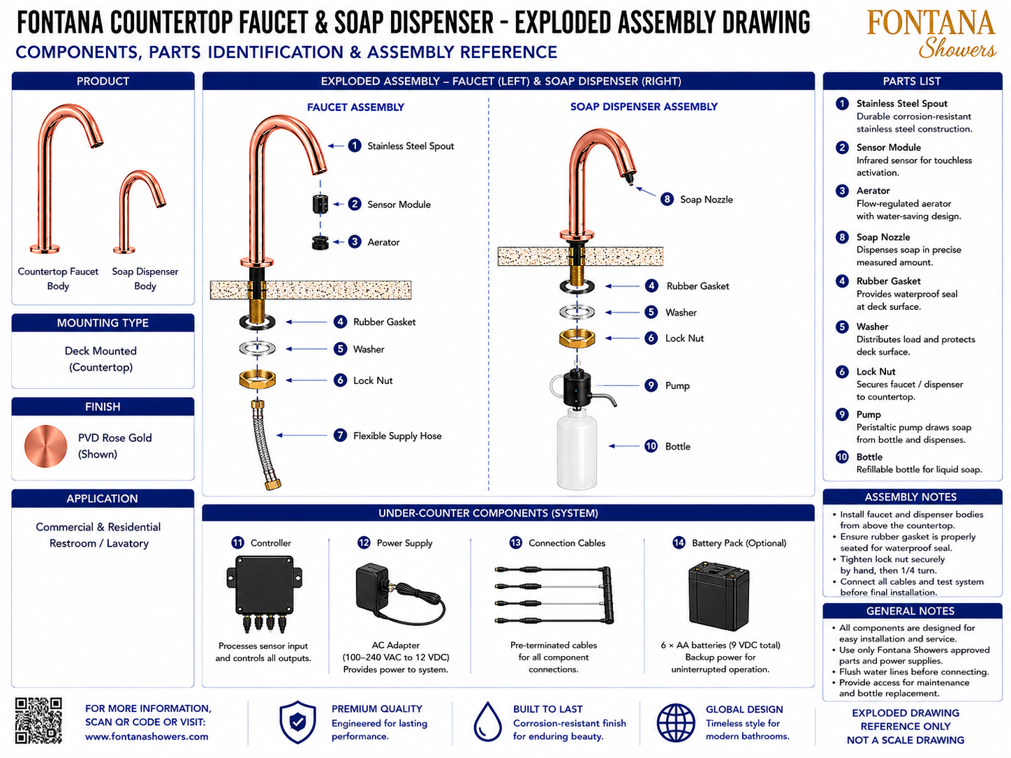
This exploded assembly resource is intended to support architects, plumbing
engineers, contractors, installers, maintenance personnel and facility managers
coordinating the Fontana countertop touchless faucet and automatic soap dispenser
within commercial and residential lavatory environments. The drawing identifies
the faucet spout, sensor module, aerator, mounting seals, washer, lock nut,
flexible supply hose, soap nozzle, pump, refillable bottle, controller,
power supply, connection cables and optional battery pack.
Fontana Touchless Faucet and Automatic Soap Dispenser Assembly
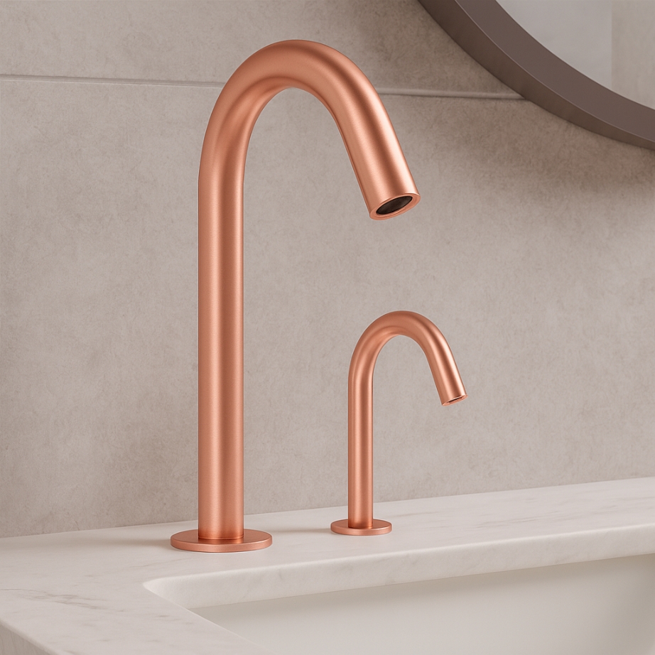
This coordinated deck-mounted fixture set combines a stainless-steel
touchless faucet and automatic soap dispenser with a rose gold PVD finish.
The exploded views clarify component order, mounting orientation and the
relationship between the visible fixtures, concealed mechanical hardware
and shared under-counter electrical system.
- Fixture set: Countertop touchless faucet and automatic soap dispenser
- Installation: Deck mounted / countertop mounted
- Finish: Rose gold PVD
- Faucet spout: Corrosion-resistant stainless steel
- Sensor module: Infrared touchless activation sensor
- Aerator: Flow-regulated water-saving outlet
- Mounting components: Rubber gasket, washer and lock nut
- Water connection: Flexible braided supply hose
- Soap-delivery components: Nozzle, peristaltic pump and refillable bottle
- System controller: Electronic control module
- Primary power: 12 VDC AC adapter
- Optional backup: 6 × AA battery pack, 9 VDC
Required Exploded Assembly Drawing Package
Each drawing should use a consistent item-numbering system, assembly axis
and component identification block. The package should clearly distinguish
the faucet assembly, soap-dispenser assembly, shared mounting components
and under-counter control system. Part orientation, assembly order,
connection points and serviceable components should be documented for
installation, commissioning, maintenance and replacement.
Exploded Assembly Overview
Shows the complete faucet assembly on the left, soap-dispenser assembly on the right and shared under-counter components below. This drawing provides an overall reference for installation, service planning and project submittals.
Faucet Spout
Identifies the visible stainless-steel spout as the primary faucet body. The spout incorporates the touchless outlet assembly and mounts through the finished countertop.
Sensor Module and Aerator
Shows the infrared sensor module and flow-regulated aerator located at the faucet outlet. These components provide touchless activation and controlled water delivery.
Faucet Mounting Stack
Illustrates the rubber gasket, washer and lock nut beneath the countertop. The components should be installed in the indicated order to seal and secure the faucet body.
Flexible Supply Hose
Identifies the braided water-supply connection attached below the faucet mounting assembly. Route the hose without kinks, abrasion or excessive tension.
Soap Nozzle and Mounting Stack
Shows the soap outlet together with the dispenser gasket, washer and lock nut. The mounting hardware secures the dispenser while maintaining a neat sealed countertop interface.
Soap Pump and Bottle
Illustrates the peristaltic pump and refillable soap reservoir beneath the dispenser. The bottle and pump should remain accessible for refilling, cleaning, inspection and replacement.
Controller and Power Supply
Identifies the electronic controller and AC adapter used to process sensor inputs and operate system outputs. Both components should be mounted in a dry, accessible under-counter location.
Connection Cables and Battery Pack
Shows the pre-terminated connection cables and optional six-AA battery backup. Keyed connectors simplify assembly and should be fully seated before the system is energized.
Engineering note:
The exploded drawing is an assembly reference and should not be scaled.
Use only approved replacement parts, power supplies and connection cables.
Verify component order, gasket seating, mounting-hardware engagement,
plumbing connections and electrical connector assignments against the
current product specification and installation instructions.
Assembly and Installation Coordination Considerations
Top-Down Installation
Insert the faucet and dispenser bodies from above the countertop before installing the seals, washers and lock nuts from below.
Gasket Seating
Ensure each rubber gasket is centered and properly seated to support a watertight interface at the finished deck surface.
Lock-Nut Tightening
Tighten each lock nut evenly and securely without over-compressing the gasket or damaging the countertop material.
Hose and Tubing Routing
Route the faucet supply hose and soap tubing independently to reduce interference and simplify inspection and maintenance.
Electrical Connections
Connect only matching keyed cables and confirm every connector is fully seated before applying power or testing the system.
Service Access
Keep the controller, power supply, battery pack, pump and bottle accessible for routine inspection, refilling and replacement.
FontanaShowers Installation and Specification Resources
FontanaShowers Product Catalog
Product information, finish options and technical documentation for Fontana touchless bathroom and commercial fixtures.
FontanaShowers Installation Hub
Central installation resource for faucets, automatic soap dispensers and related mounting and control components.
Automatic Sensor Faucet Collection
Explore touchless faucet configurations, sensor technologies, power options and commercial applications.
Faucet BIM and Design Resources
Architectural and coordination resources supporting fixture selection, project documentation and multidisciplinary model development.
Touchless Soap Dispenser Resources
Product and installation information for soap nozzles, pumps, refillable bottles and automatic dispensing systems.
Fixture Installation Resources
General installation information covering mounting, plumbing, electrical connections, testing, cleaning and maintenance.
Professional Engineering and Accessibility References
Project verification:
Exploded assembly drawings are coordination and service tools and do not replace
approved project submittals. The plumbing engineer, electrical designer,
contractor and qualified installer should verify component compatibility,
assembly order, gasket seating, mounting hardware, plumbing connections,
electrical connectors, replacement parts, service access and applicable
local codes before installation or maintenance.
|
|
|