Fontana Touchless Fixtures™ | Architectural and Engineering Resource
Fontana Countertop Faucet & Soap Dispenser:
Sensor Detection Zone
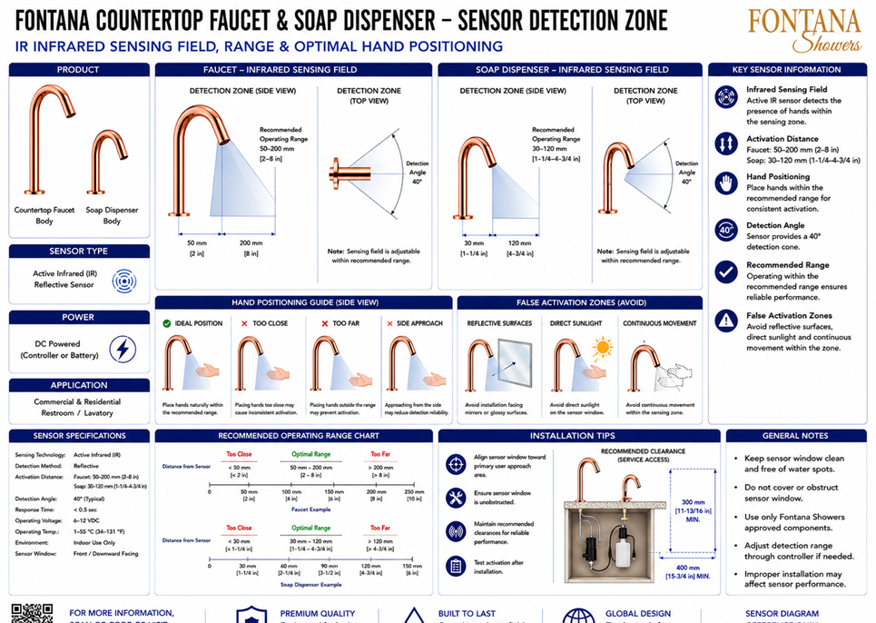
This sensor-detection resource is intended to support architects, plumbing
engineers, electrical designers, contractors, installers, commissioning
personnel and facility managers coordinating the Fontana countertop touchless
faucet and automatic soap dispenser within commercial and residential lavatory
environments. The drawing identifies the active infrared sensing fields,
recommended activation distances, detection angles, optimal hand positions,
false-activation conditions and under-counter service clearances.
Fontana Touchless Faucet and Automatic Soap Dispenser Sensor System
This coordinated touchless fixture set uses active infrared reflective
sensors to detect a user's hands within defined sensing zones. The faucet
and soap dispenser use different recommended operating ranges, while both
provide an approximate 40° detection cone. The drawing supports sensor
alignment, range adjustment, user-positioning guidance and commissioning.
- Fixture set: Countertop touchless faucet and automatic soap dispenser
- Sensor technology: Active infrared reflective sensing
- Faucet operating range: 50–200 mm (2–8 in.)
- Soap-dispenser operating range: 30–120 mm (1-1/4–4-3/4 in.)
- Detection angle: Approximately 40°
- Response time: Less than 0.5 second
- Operating voltage: 6–12 VDC
- Operating temperature: 1–55 °C (34–131 °F)
- Sensor orientation: Front / downward facing
- Environment: Indoor use only
- Vertical service clearance: 300 mm (11-13/16 in.) minimum
- Horizontal service clearance: 400 mm (15-3/4 in.) minimum
Required Sensor Detection Drawing Package
Each drawing should use a consistent sensing-field graphic, dimension style
and sensor identification block. The package should clearly distinguish the
faucet and soap-dispenser activation zones, detection angles, recommended
operating ranges, hand-positioning guidance and known false-activation
conditions. Sensor orientation and adjustment requirements should be
documented for installation, testing and commissioning.
Sensor Detection Overview
Shows the faucet and soap-dispenser sensing fields, recommended operating ranges, hand-positioning examples, false-activation zones and installation clearances. This drawing provides an overall reference for sensor coordination and commissioning.
Faucet Sensing Field
Illustrates the faucet detection zone in side and top views. The recommended operating distance extends from 50 mm to 200 mm, with an approximate 40° detection cone centered beneath the outlet.
Soap-Dispenser Sensing Field
Illustrates the dispenser detection zone in side and top views. The recommended activation distance extends from 30 mm to 120 mm, creating a compact sensing area beneath the soap nozzle.
Detection Angle
Identifies the nominal 40° sensing cone for both fixtures. The sensor window should be directed toward the primary hand-approach area and kept clear of nearby obstructions.
Optimal Hand Position
Shows hands placed naturally within the recommended sensing range. Consistent activation is achieved when the user's hands enter the center of the detection field rather than approaching from the side.
Too-Close Condition
Illustrates hand placement inside the minimum activation distance. Positioning too close to the sensor may reduce detection consistency or place the hand outside the sensor's intended reflective field.
Too-Far and Side-Approach Conditions
Shows hand positions beyond the recommended range or entering from the side. These approaches may produce delayed, intermittent or unreliable activation.
False-Activation Zones
Identifies reflective surfaces, direct sunlight and continuous movement as potential causes of unintended activation. Installation should minimize exposure to these environmental conditions.
Range Adjustment and Testing
Coordinates sensor testing after installation and adjustment through the controller where supported. Final settings should provide reliable activation without extending unnecessarily into surrounding traffic areas.
Engineering note:
The sensor diagram is a coordination reference and should not be scaled.
Keep each sensor window clean, dry and unobstructed. Verify sensing range,
detection angle, controller settings, environmental conditions and service
clearances against the current product specification and installation
instructions before final commissioning.
Sensor Installation and Commissioning Considerations
Sensor Alignment
Align each sensor toward the primary user approach so hands naturally enter the center of the intended sensing field.
Reflective Surfaces
Avoid positioning the sensor directly toward mirrors, glossy panels or other highly reflective surfaces that may return unwanted infrared signals.
Direct Sunlight
Limit direct sunlight on the sensor window because intense external light may interfere with reflective infrared detection.
Obstruction Control
Keep the sensor window and detection cone clear of accessories, splash guards, countertop objects and permanent obstructions.
Range Verification
Test activation at the minimum, midpoint and maximum recommended distances and adjust the controller only where required.
Service Access
Maintain the recommended under-counter clearance for access to the controller, power supply, sensor wiring and adjustment controls.
FontanaShowers Installation and Specification Resources
FontanaShowers Product Catalog
Product information, finish options and technical documentation for Fontana touchless bathroom and commercial fixtures.
FontanaShowers Installation Hub
Central installation resource for touchless faucets, automatic soap dispensers, sensors and related control components.
Automatic Sensor Faucet Collection
Explore touchless faucet configurations, sensing technologies, power options and commercial applications.
Faucet BIM and Design Resources
Architectural and coordination resources supporting fixture selection, project documentation and multidisciplinary model development.
Touchless Soap Dispenser Resources
Product and installation information for automatic soap dispensers, pumps, reservoirs and sensor systems.
Fixture Installation Resources
General installation information covering sensor alignment, electrical connections, testing, cleaning and maintenance.
Professional Engineering and Accessibility References
Project verification:
Sensor detection drawings are coordination and commissioning tools and do not
replace approved project submittals. The electrical designer, plumbing engineer,
contractor and qualified installer should verify sensor orientation, activation
range, detection angle, controller settings, environmental conditions, hand
approach, service access, accessibility criteria and manufacturer requirements
before installation and final commissioning.
|
|
|