Fontana Touchless Faucet Systems™ |
Architectural and Engineering Resource
Fontana DSFD0024GS Vessel Sink and Chrome Touchless Sensor Faucet:
AC / DC Power Wiring & Installation Detail
This electrical installation resource is intended to support architects,
electrical and plumbing engineers, contractors, installers and maintenance
personnel coordinating the Fontana DSFD0024GS vessel sink and chrome
touchless sensor faucet combination. The drawing package communicates
the AC 110 V power arrangement, optional DC 6 V battery operation,
low-voltage controller wiring, faucet sensor lead, solenoid connection,
hot and cold water supplies, cable routing and under-counter service
access required for reliable touchless operation.
Fontana DSFD0024GS AC / DC Touchless Faucet Power System
The DSFD0024GS touchless faucet supports both AC 110 V powered
operation and an alternate DC 6 V battery configuration. A
low-voltage electronic control module receives the faucet sensor
signal and controls the water-resistant solenoid valve. Hot and
cold water supplies connect through flexible hoses while the
power and control components remain accessible beneath the
countertop.
-
Model:
DSFD0024GS
-
Faucet type:
Touchless sensor faucet
-
Finish:
Chrome
-
Primary power option:
AC 110 V
-
Alternate power option:
DC 6 V battery
-
Battery configuration shown:
4 × AA alkaline batteries
-
Control type:
Low-voltage electronic controller
-
Valve type:
Water-resistant solenoid valve
-
Sensor connection:
Faucet sensor cable to controller
-
Solenoid connection:
Controller cable to solenoid valve
-
Water supply:
Hot and cold
-
Supply connection shown:
1/2-inch supply hose / compression arrangement
-
Installation location:
Under counter
Required AC / DC Power & Wiring Drawing Package
Each electrical coordination drawing should clearly identify the
selected power source, electronic control module, faucet sensor
cable, solenoid connection, hot / cold supply relationship and
required under-counter service access. Wiring and plumbing should
be organized so all serviceable components remain accessible after
cabinet and countertop installation.
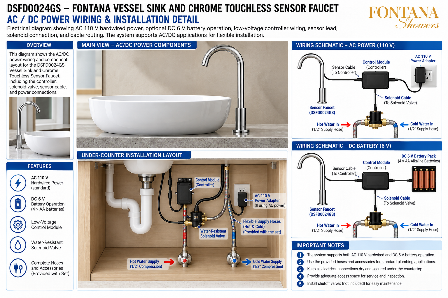
AC / DC Power Wiring & Installation Detail
Provides the complete electrical and plumbing relationship
between the touchless faucet, sensor cable, controller,
solenoid valve, power source and hot / cold water connections.
Main View — AC / DC Power Components
Shows the vessel sink and chrome touchless faucet above the
countertop with the controller, solenoid, supply hoses and
power components organized below.
Under-Counter Installation Layout
Illustrates the practical arrangement of the control module,
solenoid valve, AC adapter, flexible supply hoses, sensor
cable, drain piping and shutoff valves within the cabinet.
AC 110 V Wiring Schematic
Shows the controller powered by an AC 110 V adapter while
the faucet sensor connects to the controller and the
controller sends a low-voltage command to the solenoid valve.
DC 6 V Battery Schematic
Shows the alternate battery-powered configuration using a
DC 6 V battery pack with four AA alkaline batteries connected
to the electronic controller.
Sensor Cable to Controller
Identifies the low-voltage sensor lead connecting the faucet
to the control module so hand-detection signals can command
the water-control system.
Solenoid Control Connection
Shows the electrical lead from the controller to the
water-resistant solenoid valve that opens and closes the
water path during touchless operation.
Hot & Cold Water Connections
Coordinates separate hot and cold water inlets with flexible
1/2-inch supply hoses connected to the solenoid / mixing
assembly beneath the faucet.
Service & Inspection Access
Maintains clear access to the power adapter or battery pack,
controller, solenoid valve, wiring, supply hoses and shutoff
valves for maintenance and troubleshooting.
Engineering note:
The electrical and plumbing relationships shown are typical
installation references. Final AC power arrangement, DC battery
configuration, controller connections, solenoid wiring, hose routing,
shutoff-valve locations, electrical protection, service access and
component compatibility should be verified against the actual
Fontana DSFD0024GS components and approved installation documentation
before final installation and commissioning.
Power, Control and Wiring Coordination Considerations
AC Power Arrangement
When using AC power, position the 110 V adapter in an
accessible, dry location and route its low-voltage output
to the control module without crossing wet plumbing areas
where practical.
DC Battery Arrangement
Where battery operation is selected, keep the 6 V battery
pack accessible for replacement and away from locations
subject to leaks or standing water.
Controller Access
Mount the low-voltage controller where the sensor lead,
power connection and solenoid cable can be inspected,
disconnected and serviced without removing the countertop.
Cable Protection
Protect sensor and solenoid wiring from sharp cabinet edges,
pinch points, excessive tension, moving drawers and direct
contact with plumbing joints.
Moisture Separation
Keep electrical connectors, power components and control
wiring dry and positioned away from likely leak paths or
areas where condensation may collect.
Service Accessibility
Do not conceal the power source, controller or solenoid
behind permanent cabinet construction that prevents future
inspection or replacement.
AC 110 V Installation Considerations
Power Adapter Location
Place the AC adapter where it remains accessible for
disconnection and inspection while remaining protected
from incidental water exposure.
Controller Power Input
Confirm the power adapter is connected to the correct
controller input and that the lead is fully seated before
function testing.
Low-Voltage Routing
Route low-voltage control wiring separately from supply
hoses and drain fittings where practical to reduce the
chance of damage or moisture exposure.
Service Disconnect
Maintain convenient access to the adapter connection so
power can be disconnected before controller or solenoid
maintenance.
Outlet Coordination
Coordinate the electrical outlet location with cabinet
construction, drain piping and supply hoses so the adapter
and cord do not interfere with plumbing service.
Final AC Test
After electrical and plumbing connections are complete,
verify sensor detection, controller response, solenoid
operation and automatic water shutoff.
DC 6 V Battery Installation Considerations
Battery Pack Location
Mount the battery pack within easy reach beneath the
countertop so batteries can be replaced without removing
plumbing or cabinet components.
Battery Configuration
The drawing shows a DC 6 V pack using four AA alkaline
batteries. Verify polarity and the actual supplied battery
holder before commissioning.
Moisture Protection
Keep the battery pack clear of supply fittings, drain
connections and cabinet areas where water could accumulate.
Cable Slack
Provide enough cable slack for battery-pack removal and
replacement without placing tension on the controller
connection.
Battery Maintenance
Inspect the battery pack periodically and replace batteries
as required to maintain reliable sensor and solenoid
operation.
Final DC Test
Verify the controller powers correctly from the battery
pack and confirm reliable faucet activation and shutoff
before project handover.
Final Wiring & Commissioning Verification
Power Source Check
Confirm the selected AC 110 V or DC 6 V power source is
connected correctly and supplying the controller.
Sensor Connection Check
Verify the faucet sensor lead is fully connected to the
control module and remains free from pinching or damage.
Solenoid Connection Check
Confirm the solenoid control cable is securely connected
and the valve opens and closes in response to the controller.
Water-Supply Check
Verify hot and cold flexible hoses are connected correctly,
free from kinks and leak-free under normal operating pressure.
Touchless Function Test
Place a hand within the sensing field and confirm prompt
water activation, stable delivery and proper automatic
shutoff when the hand is removed.
Service Access Check
Confirm the final cabinet installation leaves the controller,
solenoid valve, power source, hoses and shutoff valves
accessible for future inspection and maintenance.
FontanaShowers Installation and Specification Resources
Professional Engineering and Electrical References
Project verification:
AC / DC power and wiring drawings are coordination tools and do not
replace approved project submittals or manufacturer instructions.
The architect, electrical engineer, plumbing engineer, contractor and
licensed installer should verify power requirements, outlet location,
battery configuration, controller wiring, solenoid connection, sensor
lead routing, moisture protection, hot / cold water connections,
service access and locally adopted electrical and plumbing requirements
before final installation and commissioning.
|
|
|