Fontana Accessible Touchless Faucet Systems™ |
Architectural and Engineering Resource
Fontana DSFD0024GS Vessel Sink and Chrome Touchless Sensor Faucet:
ADA Coordination Drawing
This accessibility-focused coordination resource is intended to support
architects, plumbing engineers, interior designers, contractors,
accessibility consultants and installers coordinating the Fontana
DSFD0024GS vessel sink and chrome touchless sensor faucet combination.
The drawing package communicates vessel-sink placement, faucet reach,
touchless sensor use zone, forward approach, clear floor space,
knee clearance, toe clearance, counter height and under-counter
plumbing coordination for accessible use.
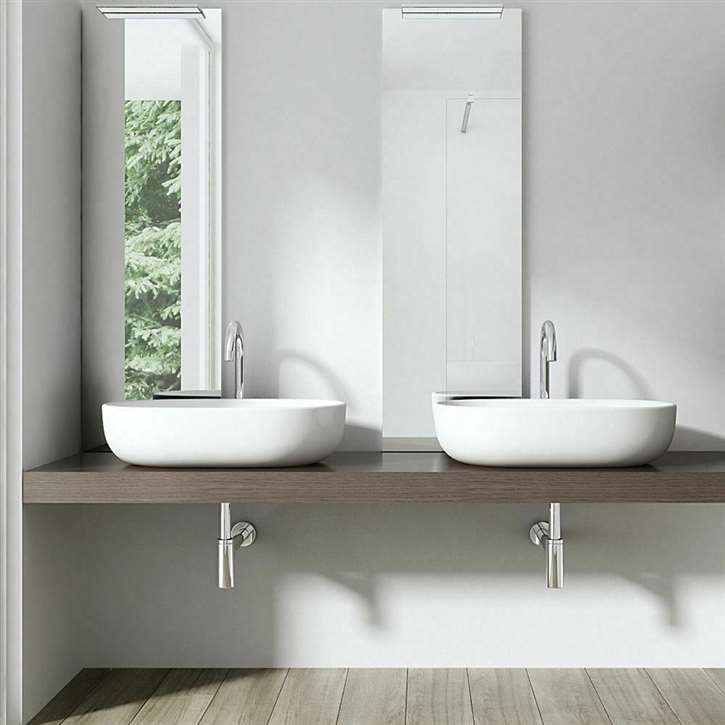
Fontana DSFD0024GS Accessible Vessel Sink & Touchless Faucet Coordination
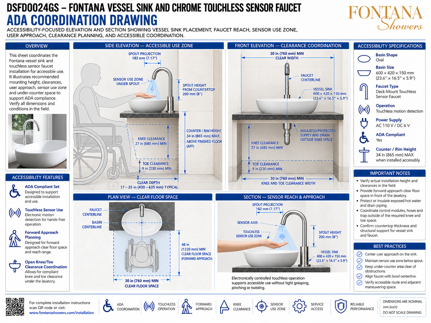
The DSFD0024GS accessibility drawing coordinates the white oval
vessel sink, chrome touchless faucet, user approach and under-counter
clearances as a complete installation. The faucet centerline,
sensor-use area, basin position, clear floor space and protected
plumbing are shown together so accessibility and serviceability
can be reviewed before fabrication and final installation.
-
Model:
DSFD0024GS
-
Basin shape:
Oval
-
Basin size:
600 × 420 × 150 mm
(23.6 × 16.5 × 5.9 in.)
-
Faucet type:
Deck-mount touchless sensor faucet
-
Operation:
Touchless motion detection
-
Power supply:
AC 110 V / DC 6 V
-
Spout projection:
182 mm (7.17 in.)
-
Spout height above countertop:
200 mm (8 in.)
-
Maximum counter / rim height:
34 in. (865 mm) AFF
-
Minimum knee clearance:
27 in. (685 mm)
-
Minimum toe clearance:
9 in. (230 mm)
-
Typical clear depth:
17–25 in. (430–635 mm)
-
Minimum clear width:
30 in. (760 mm)
-
Forward-approach clear floor space:
30 × 48 in. (760 × 1220 mm)
-
Sensor-use zone:
Beneath the spout
Required ADA & Accessibility Coordination Drawing Package
Each accessibility coordination drawing should use a consistent
finished-floor datum, faucet centerline, basin centerline and clear
floor-space reference. The package should clearly identify counter
height, faucet reach, sensor-use zone, forward approach, knee
clearance, toe clearance, clear width, protected plumbing and
under-counter equipment placement before final installation.
ADA Coordination Drawing
Provides the complete relationship between the vessel sink,
touchless faucet, sensor-use zone, forward approach, clear
floor space, counter height and under-counter clearance.
Side Elevation — Accessible Use Zone
Shows the seated user relationship to the basin, faucet,
sensor zone, 34-inch maximum counter / rim height,
27-inch knee clearance and 9-inch toe clearance.
Faucet Reach & Sensor Zone
Shows the approximately 182 mm (7.17 in.) spout projection,
200 mm (8 in.) spout height and touchless sensing area beneath
the spout for comfortable hand entry.
Front Elevation — Clearance Coordination
Identifies the minimum 30-inch (760 mm) clear width beneath
the lavatory and the faucet centerline aligned with the
vessel sink.
Knee Clearance
Shows a minimum knee-clearance height of approximately
27 inches (685 mm) beneath the countertop for forward
wheelchair approach.
Toe Clearance
Shows a minimum toe-clearance height of approximately
9 inches (230 mm) coordinated with the required clear
depth under the lavatory.
Plan View — Clear Floor Space
Illustrates the minimum 30 × 48 inch
(760 × 1220 mm) clear floor-space area centered on the
lavatory for forward approach.
Sensor Reach & Approach
Shows the user hand entering the touchless sensor field
without requiring grasping, pinching or twisting of a
manual control.
Protected Plumbing Coordination
Identifies supply and drain piping within the accessible
under-counter zone and indicates that exposed plumbing
should be insulated or otherwise protected where required.
Engineering note:
The dimensions shown are coordination references from the illustrated
DSFD0024GS accessibility drawing. Final counter height, clear floor
space, knee and toe clearance, plumbing protection, faucet reach,
sensor location and accessible-route requirements should be verified
against the actual installation, approved project documents and
applicable accessibility requirements before final installation.
Accessible Use & Fixture Coordination Considerations
Counter / Rim Height
Coordinate the installed countertop and vessel-sink rim so
the accessible-use height shown in the drawing is maintained
after all finished surfaces are installed.
Forward Approach
Keep the floor area in front of the lavatory clear so the
user can approach the sink directly from the front without
fixed obstructions.
Knee Space
Keep cabinet framing, controllers, hoses and other components
out of the required knee-clearance envelope wherever practical.
Toe Space
Maintain the required toe-clearance zone beneath the
lavatory and avoid placing fixed plumbing or millwork
within the user's foot area.
Touchless Sensor Reach
Position the faucet so the user can comfortably place a
hand within the sensing field without excessive forward
reach over the vessel rim.
Faucet & Basin Alignment
Align the faucet and basin centerlines to keep the water
stream and sensor-use zone within the most accessible
portion of the vessel.
Knee, Toe & Clear Floor Space Coordination
30-Inch Clear Width
Maintain at least the illustrated 30-inch
(760 mm) clear width beneath and in front of the lavatory
where required by the project.
48-Inch Forward Approach
Keep the illustrated 48-inch (1220 mm) forward-approach
depth unobstructed so a wheelchair user can position
directly in front of the fixture.
27-Inch Knee Height
Maintain the illustrated minimum 27-inch (685 mm)
knee-clearance height beneath the accessible lavatory.
9-Inch Toe Height
Keep the illustrated minimum 9-inch (230 mm) toe-clearance
zone open beneath the front portion of the lavatory.
Clear Depth
Coordinate the illustrated 17–25 inch (430–635 mm)
clear-depth range with plumbing, cabinetry and structural
supports beneath the sink.
Unobstructed Floor Area
Avoid fixed accessories, waste bins, cabinetry or other
items within the required clear floor-space envelope.
Under-Counter Plumbing & Equipment Coordination
Protected Supply Piping
Protect exposed hot-water supply piping within the accessible
knee space as indicated by the project requirements.
Protected Drain Piping
Coordinate and protect drain piping so the trap and tailpiece
do not create an obstruction or contact hazard within the
accessible use zone.
Control Module Placement
Locate electronic control modules outside the required
knee and toe clearance where practical while maintaining
accessible service space.
Hose Routing
Route hot and cold supply hoses so they do not project
unnecessarily into the accessible knee-space envelope.
Trap Coordination
Coordinate the trap and wall-drain connection with the
clearance envelope before closing walls or installing
permanent cabinetry.
Service Access
Maintain access to plumbing and electronic components
without compromising the required user clearance beneath
the lavatory.
Touchless Sensor & User Operation Coordination
Sensor Use Zone
Keep the touchless sensing zone directly beneath the spout
and within comfortable reach from the illustrated forward
approach position.
Hands-Free Operation
The electronic sensor arrangement allows water activation
without requiring manual grasping, pinching or twisting
of a conventional faucet control.
Spout Projection
Coordinate the approximately 182 mm (7.17 in.) spout
projection with the vessel rim and user approach so the
water outlet remains comfortably reachable.
Water Landing Zone
Keep the faucet outlet aligned with the usable center of
the vessel so the stream remains inside the bowl during
accessible use.
Sensor Commissioning
After installation, verify the sensor detects a user's hand
from the intended accessible approach without excessive
reaching.
Clear Approach
Avoid soap dispensers, accessories or fixed objects that
interfere with the user's forward reach toward the touchless
sensing zone.
Accessibility Installation Best Practices
Verify Finished Height
Check actual finished-floor, countertop and vessel-rim
elevations before final fixture installation.
Maintain Clear Floor Space
Keep the illustrated forward-approach zone free from
fixed cabinets, accessories and storage items.
Protect Plumbing
Insulate or otherwise protect exposed water-supply and
drain components within the user clearance zone as required.
Keep Equipment Outside Knee Space
Coordinate controllers, power components, hoses and service
access so they do not unnecessarily reduce the required
knee or toe clearances.
Verify Sensor Reach
Test sensor response from the intended user position and
confirm operation without excessive reach or awkward hand
placement.
Field Verification
Confirm all clearances, heights and access conditions in
the field before project handover.
FontanaShowers Installation and Specification Resources
Professional Accessibility and Plumbing References
Project verification:
ADA and accessibility coordination drawings are design tools and do not
replace approved project documents, governing accessibility standards
or manufacturer instructions. The architect, accessibility consultant,
plumbing engineer, contractor and licensed installer should verify
counter / rim height, clear floor space, knee and toe clearance,
faucet reach, sensor operation, plumbing protection, control-module
location, accessible route and all applicable project requirements
before final installation and commissioning.
|
|
|