Fontana Touchless Faucets™ | Architectural and Engineering Resource
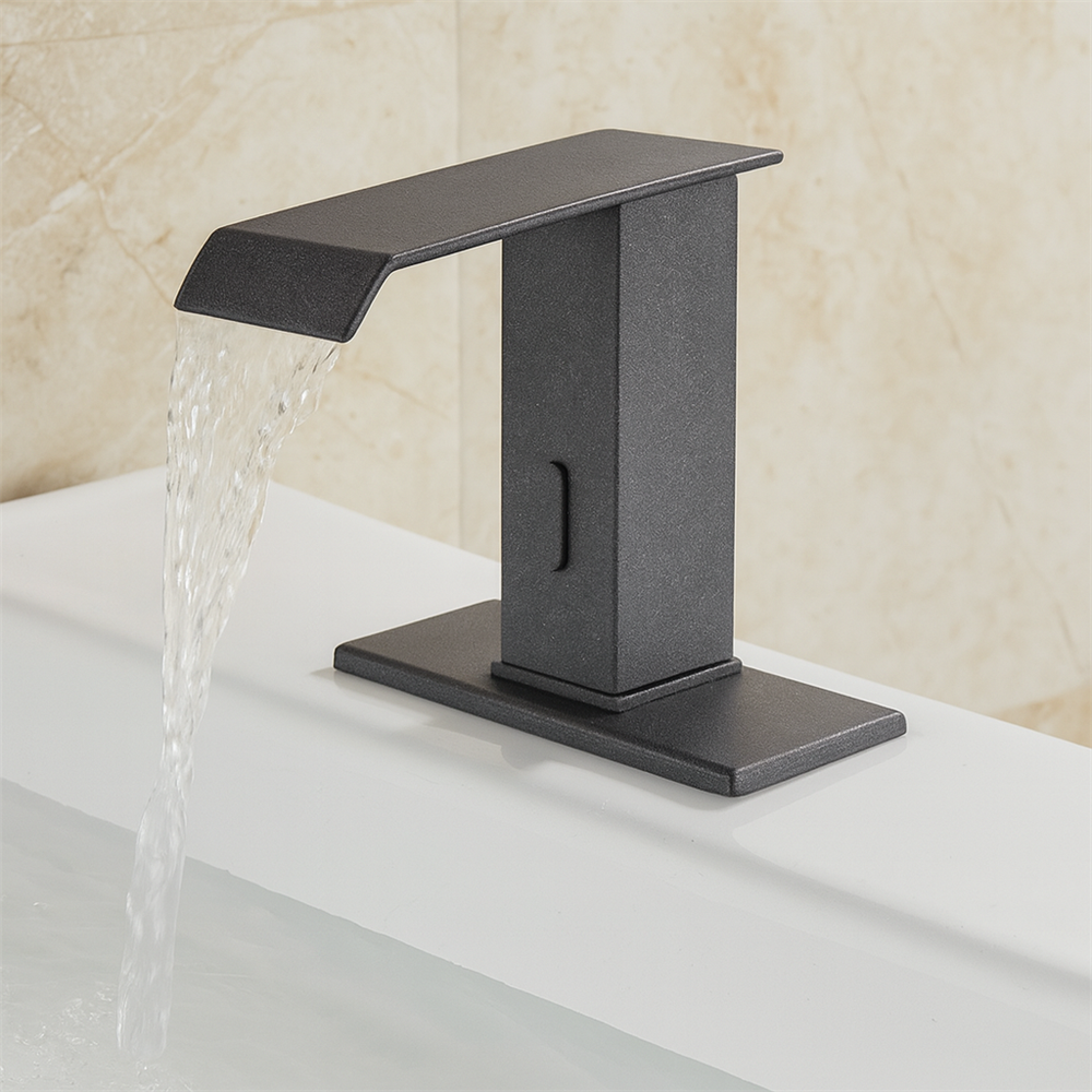
Fontana Lymora FS9099BGR Black Granite Automatic Motion Sensor Faucet:
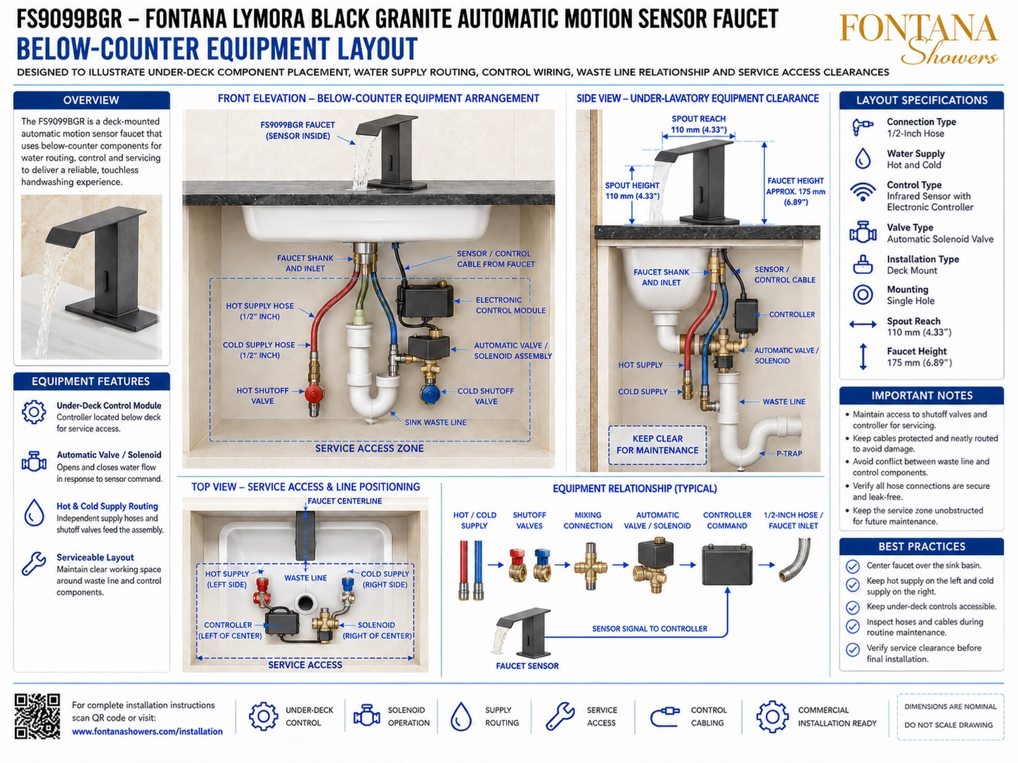
Below-Counter Equipment Layout
This below-counter coordination resource is intended to support architects,
plumbing engineers, contractors, installers, millwork coordinators and facility
managers coordinating the Fontana Lymora FS9099BGR Black Granite automatic
motion-sensor faucet. The drawing package communicates the under-deck controller,
automatic solenoid valve, hot and cold supply routing, shutoff valves, sensor
cabling, faucet inlet, sink waste line, P-trap relationship and service-access
clearances required for a maintainable installation.
Fontana Lymora FS9099BGR Under-Deck Equipment Arrangement
The FS9099BGR uses below-counter components to manage water routing,
sensor control and automatic valve operation. The recommended layout
keeps the electronic controller and solenoid assembly accessible while
preserving clear space around the drain and P-trap for future plumbing
and controls maintenance.
- Model: FS9099BGR
- Finish: Black Granite
- Connection type: 1/2-inch hose
- Water supply: Hot and cold
- Control type: Infrared sensor with electronic controller
- Valve type: Automatic solenoid valve
- Installation: Single-hole deck mount
- Spout reach: 110 mm (4.33 in.)
- Overall faucet height: Approximately 175 mm (6.89 in.)
- Primary service components: Controller, solenoid, shutoff valves and hoses
- Drainage coordination: Maintain clear access around waste line and P-trap
Required Below-Counter Equipment Drawing Package
Each below-counter drawing should use a consistent faucet centerline,
component-identification scheme and service-access notation. The package
should clearly identify the controller, solenoid valve, hot and cold supply
lines, shutoff valves, hose routing, control cable, faucet inlet, waste line,
P-trap and unobstructed maintenance zone required after cabinetry and fixture
installation are complete.
Below-Counter Equipment Layout
Shows the complete under-deck arrangement for the Fontana Lymora FS9099BGR, including the faucet shank and inlet, hot and cold supply hoses, shutoff valves, electronic controller, automatic solenoid valve, sensor / control cable, sink waste line, P-trap and the recommended service-access zone.
Front Elevation — Equipment Arrangement
Illustrates the faucet centered over the lavatory with the principal service components organized below the countertop. The control module and solenoid are positioned to remain accessible while the waste line and P-trap retain a clear removal path.
Under-Deck Control Module
Identifies the electronic controller below the deck as the interface between the infrared sensor and the automatic valve. It should be mounted in a dry, accessible location clear of drainage piping and sharp edges.
Automatic Valve / Solenoid
Shows the automatic valve assembly near the faucet inlet and supply routing. The solenoid should remain accessible for inspection, leak testing, removal, replacement and control-connection checks.
Hot & Cold Supply Routing
Maintains hot water on the left and cold water on the right with dedicated shutoff valves. Flexible hoses should follow smooth paths without kinks, twisting, excessive tension or interference with the waste system.
Top View — Service Access & Line Positioning
Shows the hot supply on the left, cold supply on the right, controller left of center, solenoid right of center and the waste line near the middle. This arrangement helps separate serviceable controls from the drain assembly.
Side View — Under-Lavatory Clearance
Illustrates the vertical relationship between the faucet shank, control cable, controller, solenoid, water supplies, basin, waste pipe and P-trap. The area beneath the faucet should remain open for technician access.
Waste-Line Coordination
Coordinates the controller, solenoid, hoses and cable around the sink drain and P-trap. Components should not block trap removal, contact sharp pipe edges or sit where condensation can drip onto electronics.
Service Access & Final Verification
Before handover, verify accessible shutoff valves, removable solenoid, reachable controller, kink-free hoses, protected control wiring, unobstructed P-trap access and a clear under-deck working zone.
Engineering note:
All component positions shown are nominal coordination references. Final
controller location, solenoid placement, hose routing, cable path,
waste-line arrangement, cabinet dimensions and service clearances should
be verified against the actual lavatory, millwork conditions and approved
Fontana Lymora FS9099BGR installation documentation before final installation.
Plumbing, Controls and Millwork Coordination Considerations
Service Access Zone
Maintain a clear working area beneath the basin so the shutoff valves, controller, solenoid, hoses, faucet shank and waste fittings can be reached without removing permanent cabinetry.
Controller Placement
Mount the electronic controller in a dry and accessible location away from the waste line and potential condensation while keeping sensor wiring organized.
Solenoid Placement
Keep the automatic valve in a serviceable position where it can be isolated, tested and removed without interference from the P-trap or cabinet framing.
Supply Routing
Keep hot supply on the left and cold supply on the right, using smooth hose bends and sufficient slack for installation and maintenance.
Waste-Line Clearance
Preserve a clear path around the drain and P-trap so plumbing components can be removed independently of the faucet-control equipment.
Cable Protection
Route sensor / control cables away from sharp edges, hot surfaces, pinch points and standing water, while maintaining enough slack for future servicing.
FontanaShowers Installation and Specification Resources
Professional Engineering and Accessibility References
Project verification:
Below-counter equipment-layout drawings are coordination tools and do not
replace approved project submittals. The architect, plumbing engineer,
millwork coordinator, contractor and licensed installer should verify
controller position, solenoid access, hot / cold routing, shutoff-valve
accessibility, control-cable protection, waste-line clearance, P-trap
serviceability, cabinet dimensions and locally adopted plumbing requirements
before final installation and commissioning.
|
|
|