Fontana Commercial Touchless Faucets™ | Architectural and Engineering Resource
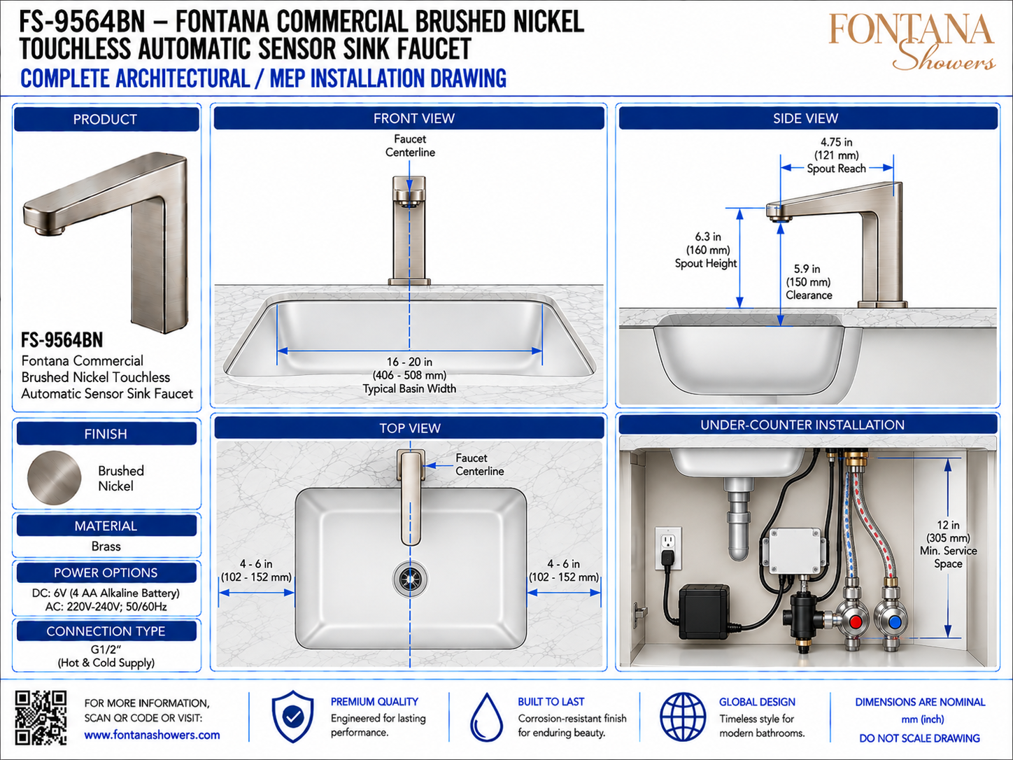
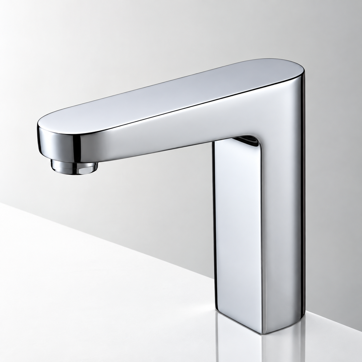
Fontana FS-9564BN Commercial Brushed Nickel Touchless Automatic Sensor Sink Faucet:
Complete Architectural / MEP Installation Drawing
This complete architectural and MEP installation resource is intended to support
architects, plumbing engineers, electrical engineers, interior designers,
contractors, installers and facility managers coordinating the Fontana FS-9564BN
commercial touchless automatic sensor sink faucet. The drawing package consolidates
front, side and top views with basin positioning, countertop clearances, spout
reach, spout height, under-counter plumbing, power/control components and minimum
service access into a single coordinated reference.
Fontana FS-9564BN Complete Architectural & MEP Coordination Reference
The FS-9564BN combines a deck-mounted touchless faucet with coordinated
architectural, plumbing, electrical and service requirements. This drawing
provides a consolidated view for fixture positioning, basin alignment,
countertop fabrication, water-supply routing, power/control placement and
long-term maintenance access.
- Model: FS-9564BN
- Fixture type: Touchless automatic sensor sink faucet
- Installation: Deck mounted / countertop mounted
- Finish: Brushed nickel
- Material: Brass
- Typical basin width: 406–508 mm (16–20 in.)
- Spout reach: 121 mm (4.75 in.)
- Spout height: Approximately 160 mm (6.3 in.)
- Vertical clearance: Approximately 150 mm (5.9 in.)
- Side countertop spacing: Approximately 102–152 mm (4–6 in.)
- Minimum service space: 305 mm (12 in.)
- Water connections: G1/2 hot and cold supply
Required Complete Architectural / MEP Drawing Package
Each drawing should use a consistent centerline convention, dimension style and
component-identification system. The package should clearly coordinate faucet and
basin geometry, countertop dimensions, spout reach and height, under-counter
plumbing, control equipment, power source and maintenance clearances so architectural
and MEP teams can verify installation requirements before fabrication and rough-in.
Complete Architectural / MEP Overview
Combines the primary above-counter and below-counter requirements into one coordinated reference for architectural, plumbing, electrical and installation teams.
Front View
Shows the faucet aligned on the basin centerline and identifies a typical basin width of 406–508 mm (16–20 in.) for coordinated lavatory planning.
Side View
Illustrates the 121 mm (4.75 in.) spout reach, approximate 160 mm (6.3 in.) spout height and approximately 150 mm (5.9 in.) vertical clearance shown in the installation condition.
Top View
Shows the faucet aligned with the basin centerline and illustrates approximately 102–152 mm (4–6 in.) of countertop area on each side of the depicted basin.
Faucet & Basin Centerline Coordination
Establishes the relationship between faucet centerline, basin centerline and drain location so the water stream enters the intended wash area.
Under-Counter Plumbing Layout
Shows the hot and cold supply connections, braided hoses and under-counter plumbing arrangement required to serve the touchless faucet system.
Control & Power Components
Identifies the control box, solenoid valve and power source beneath the countertop and supports coordinated electrical and plumbing routing.
Minimum Service Access
Shows a minimum 305 mm (12 in.) service space so key components remain accessible for inspection, troubleshooting and replacement.
Installation Verification
Confirms that faucet positioning, basin dimensions, plumbing, electrical components and service access have been coordinated before drilling, fabrication and final installation.
Engineering note:
The complete architectural / MEP installation drawing is provided for coordination
reference only. Verify field conditions and approved product data before installation;
maintain accessible under-counter service space; coordinate plumbing and electrical
work with the cabinet layout; keep hoses and wiring clear of the drain assembly;
confirm basin and faucet centerlines before drilling; and do not scale dimensions
directly from the drawing.
Architectural, Plumbing and Electrical Coordination Considerations
Basin Alignment
Coordinate the faucet centerline and 121 mm spout reach with the selected basin so the outlet and sensor operate within the intended wash area.
Countertop Fabrication
Verify basin cutout, faucet location, side clearances and mounting conditions before countertop fabrication or field drilling.
Plumbing Rough-In
Coordinate G1/2 hot and cold supplies, shutoff locations, hose routing and drain geometry so all components remain accessible and conflict-free.
Electrical / Control Routing
Position the control box, power source and control wiring away from potential leak paths and maintain clear separation from plumbing components.
Service Clearance
Maintain the illustrated 305 mm (12 in.) minimum service zone so the control box, valve, power source and supply connections can be reached for maintenance.
Final Commissioning
Before handover, verify fixture alignment, secure plumbing and electrical connections, reliable sensor activation, correct valve operation and leak-free performance.
FontanaShowers Installation and Specification Resources
Professional Engineering and Accessibility References
Project verification:
Complete architectural / MEP installation drawings are coordination tools and do
not replace approved project submittals. The architect, plumbing engineer, electrical
engineer, countertop fabricator, contractor and qualified installer should verify
basin dimensions, faucet centerline, spout reach, countertop clearances, water-supply
connections, control/power components, service access, accessibility criteria and
locally adopted codes before fabrication or installation.
|
|
|