Fontana Commercial Touchless Faucets™ | Architectural and Engineering Resource
Fontana FS-9564BN Commercial Brushed Nickel Touchless Automatic Sensor Sink Faucet:
Electrical / Power Connection Diagram
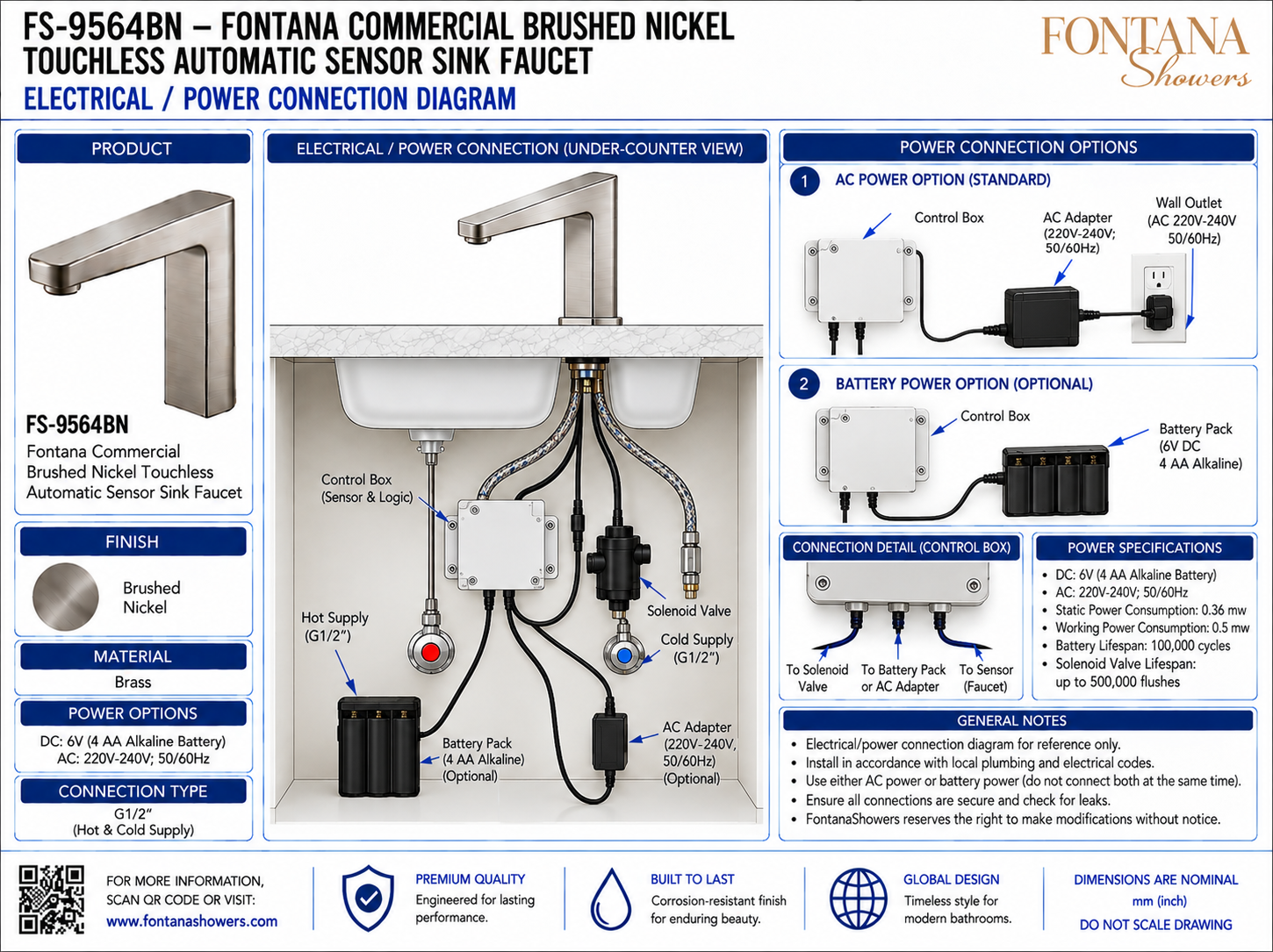
This electrical and power-connection resource is intended to support architects,
electrical engineers, plumbing engineers, contractors, installers and facility
managers coordinating the Fontana FS-9564BN commercial touchless automatic sensor
sink faucet. The drawing package communicates the under-counter relationship between
the faucet sensor, control box, solenoid valve, hot and cold G1/2 water supplies,
AC adapter, optional battery pack and the dedicated connection points required for
power, sensing and automatic valve operation.
Fontana FS-9564BN Electrical & Power Control System
The FS-9564BN uses a control box to coordinate the infrared faucet sensor,
solenoid valve and selected power source beneath the countertop. The system
may be powered by the illustrated AC adapter or by an optional 6V battery
pack, with each connection routed directly to the control box for reliable
touchless operation.
- Model: FS-9564BN
- Fixture type: Touchless automatic sensor sink faucet
- Control component: Control box / sensor logic
- Valve component: Solenoid valve
- AC input: 220–240V, 50/60Hz
- Battery option: DC 6V (4 AA alkaline batteries)
- Static power consumption: 0.36 mW
- Working power consumption: 0.5 mW
- Battery service reference: Up to 100,000 cycles
- Solenoid valve service reference: Up to 500,000 flushes
- Water connections: G1/2 hot and cold supply
- Power selection: Use AC or battery power, not both simultaneously
Required Electrical / Power Connection Drawing Package
Each drawing should use a consistent component identification system and clearly
distinguish power, sensor and valve connections. The package should identify the
control box, faucet sensor lead, solenoid-valve connection, AC-adapter input,
optional battery-pack connection and associated under-counter routing. The selected
power method should remain accessible for inspection, commissioning and maintenance.
Under-Counter Electrical Layout
Shows the installed relationship between the faucet, control box, solenoid valve, supply lines, battery pack and AC adapter. This view provides the primary reference for coordinating plumbing and electrical components beneath the countertop.
AC Power Option
Illustrates the standard AC-power arrangement from the control box through the 220–240V, 50/60Hz adapter to the wall outlet. The adapter and cable should remain dry and accessible for service.
Battery Power Option
Shows the optional 6V DC battery pack using four AA alkaline batteries connected directly to the control box. Position the pack where battery replacement can be completed without disturbing plumbing components.
Control Box Connection Detail
Identifies the dedicated connections leading from the control box to the solenoid valve, selected power source and faucet sensor. Connectors should be fully seated and protected from moisture.
Solenoid Valve Connection
Shows the control lead from the control box to the automatic water valve. The cable should be routed without pinching, excessive tension or contact with hot surfaces.
Faucet Sensor Connection
Identifies the sensor lead between the faucet and the control box. Maintain a clean routing path and avoid sharp bends that could strain the cable or connector.
Power Specifications
Documents the DC 6V battery option, 220–240V AC option, static and working power consumption values, and the indicated battery and solenoid service-cycle references.
Power-Source Selection
Use either the AC adapter or the battery pack according to the project requirements. Do not connect both power sources to the control box at the same time.
Electrical Commissioning
After installation, verify secure power connections, reliable sensor response, correct solenoid-valve operation and stable automatic faucet performance before placing the fixture into service.
Engineering note:
The electrical/power connection diagram is a coordination reference and should
not be scaled. Verify power-source compatibility, wall-outlet requirements,
control-box connections, sensor wiring, solenoid-valve wiring and service access
against the current FontanaShowers installation instructions and approved project
submittal before installation.
Electrical, Plumbing and Service Coordination Considerations
Power-Source Strategy
Select either AC or battery operation based on project requirements and maintain a clear, documented power arrangement beneath the countertop.
Outlet Location
When AC power is used, coordinate the wall outlet and adapter position so the cord reaches the control box without extension, strain or exposure to water.
Cable Routing
Keep power, sensor and valve cables away from sharp cabinet edges, moving hardware and plumbing connections that could cause abrasion or damage.
Moisture Protection
Locate the control box, adapter, battery pack and electrical connectors away from likely leak paths and direct water exposure.
Service Access
Maintain sufficient cabinet clearance to reach all connectors, replace batteries, disconnect the adapter and service the solenoid valve without removing the faucet.
Final Functional Test
Verify the selected power source, sensor detection, valve actuation and automatic shutoff through repeated activation cycles before handover.
FontanaShowers Installation and Specification Resources
Professional Engineering and Accessibility References
Project verification:
Electrical and power-connection drawings are coordination tools and do not replace
approved project submittals. The architect, electrical engineer, plumbing engineer,
contractor and qualified installer should verify power-source compatibility,
outlet requirements, control-box connections, battery configuration, sensor wiring,
solenoid-valve wiring, service access, accessibility criteria and locally adopted
codes before installation and commissioning.
|
|
|