Fontana Commercial Touchless Faucets™ | Architectural and Engineering Resource
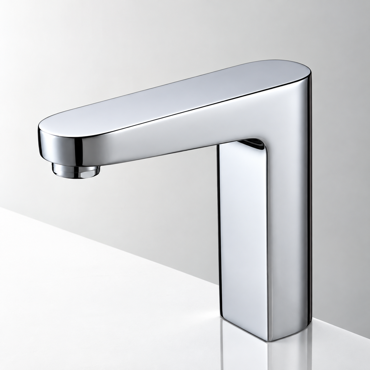
Fontana FS-9564BN Commercial Brushed Nickel Touchless Automatic Sensor Sink Faucet:
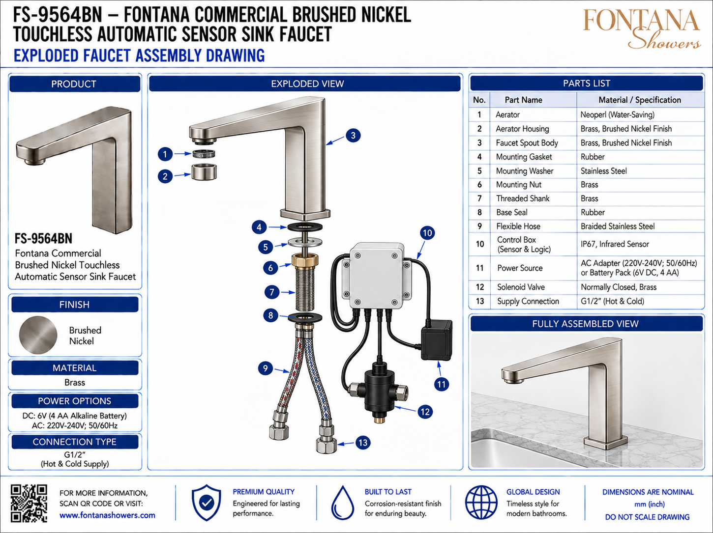
Exploded Faucet Assembly Drawing
This exploded faucet assembly resource is intended to support architects,
plumbing engineers, contractors, installers, service technicians and facility
managers coordinating the Fontana FS-9564BN touchless automatic sensor sink
faucet. The drawing package identifies the principal mechanical, mounting,
plumbing, sensing, power and control components from the outlet assembly through
the under-counter system, providing a clear reference for installation,
component identification, maintenance and replacement-part coordination.
Fontana FS-9564BN Exploded Faucet Assembly & Parts Reference
The FS-9564BN combines a brushed-nickel brass faucet body with concealed
mounting hardware, braided supply hoses, infrared sensor control, a
normally closed solenoid valve and selectable AC or battery power. The
exploded view provides a practical component-identification reference for
installation sequencing, troubleshooting and future service.
- Model: FS-9564BN
- Fixture type: Touchless automatic sensor sink faucet
- Finish: Brushed nickel
- Material: Brass faucet body
- Outlet assembly: Aerator and aerator housing
- Mounting assembly: Gasket, washer, nut, threaded shank and base seal
- Supply hoses: Braided stainless steel
- Control box: Sensor and logic module
- Power options: AC adapter or 6V DC battery pack
- Valve type: Normally closed solenoid valve
- Supply connection: G1/2 hot and cold
- Primary use: Installation, service and parts identification
Required Exploded Faucet Assembly Drawing Package
Each drawing should use a consistent part-numbering system and clearly identify
the assembly order from the faucet outlet through the countertop mounting stack
and under-counter controls. The package should distinguish mechanical parts,
seals, threaded hardware, supply hoses, sensor/control components, power source
and solenoid valve connections so installers and service personnel can trace each
component throughout the system.
Exploded Faucet Assembly
Shows the full FS-9564BN assembly from the aerator and faucet body through the mounting stack, flexible hoses, control box, power source, solenoid valve and G1/2 supply connections.
Aerator & Housing
Identifies the water-saving aerator and brushed-nickel aerator housing at the faucet outlet. These components regulate and shape the discharge stream and may require periodic cleaning or replacement.
Faucet Spout Body
Shows the main brushed-nickel brass faucet body, including the deck-mounted base and integrated sensor area that form the visible above-counter fixture assembly.
Mounting Gasket & Base Seal
Identifies the rubber sealing components located at the mounting interface. Correct placement helps stabilize the faucet and reduce moisture migration around the countertop penetration.
Mounting Washer & Nut
Shows the stainless-steel mounting washer and brass mounting nut used beneath the countertop to clamp the faucet securely in position.
Threaded Shank
Identifies the brass threaded shank passing through the countertop. It provides the structural connection for the mounting hardware and routes the supply assembly below the deck.
Flexible Supply Hoses
Shows the braided stainless-steel flexible hoses connecting the faucet assembly to the under-counter water-control system. Hoses should remain free from kinks, abrasion and excessive tension.
Control Box & Power Source
Identifies the sensor/logic control box and selected power source. The system may use the illustrated AC adapter or compatible battery pack according to the installation configuration.
Solenoid Valve & Supply Connection
Shows the normally closed solenoid valve and G1/2 hot/cold supply connection. The valve automatically controls water flow in response to commands from the sensor/control system.
Engineering note:
The exploded assembly drawing is provided for component identification and
coordination only. Do not scale the image. Verify part configuration, seal
placement, mounting-hardware order, hose connections, control-box wiring,
power-source compatibility and solenoid-valve connections against the current
FontanaShowers installation instructions and approved product documentation
before assembly or service.
Installation, Service and Parts Coordination Considerations
Assembly Sequence
Install components in the order shown, beginning with the faucet body and mounting seals, then securing the washer and nut before completing hoses, controls and power connections.
Seal Placement
Confirm the mounting gasket and base seal are positioned correctly and remain flat so the faucet seats evenly against the countertop.
Mounting Security
Tighten the mounting nut evenly to prevent fixture movement while avoiding excessive force that could damage the countertop or mounting hardware.
Hose Routing
Route braided supply hoses with smooth bends and maintain clearance from drain piping, cabinet hardware and electrical connectors.
Service Identification
Use the numbered parts list when ordering replacements or diagnosing the system so mechanical, electrical and water-control components can be identified consistently.
Final Functional Test
After reassembly, verify secure connections, leak-free plumbing, reliable sensor response and correct solenoid-valve operation before returning the faucet to service.
FontanaShowers Installation and Specification Resources
Professional Engineering and Accessibility References
Project verification:
Exploded assembly drawings are component-identification and coordination tools and
do not replace approved project submittals. The architect, plumbing engineer,
contractor, service technician and qualified installer should verify part
configuration, mounting sequence, seal placement, hose routing, control-box
connections, power-source compatibility, solenoid-valve operation, accessibility
criteria and locally adopted codes before assembly, installation or service.
|
|
|