Fontana Commercial Touchless Faucets™ | Architectural and Engineering Resource
Fontana FS-9564BN Commercial Brushed Nickel Touchless Automatic Sensor Sink Faucet: Service & Maintenance Access Drawing
This service and maintenance access resource is intended to support architects, plumbing engineers, electrical engineers, contractors, installers, service technicians and facility managers coordinating the Fontana FS-9564BN commercial touchless automatic sensor sink faucet. The drawing package communicates the recommended under-counter service area, minimum working clearance, accessible control box, solenoid valve, power source, hot and cold G1/2 supply connections, and the basic access, service and reinstallation process.
Fontana FS-9564BN Service & Maintenance Access Guide
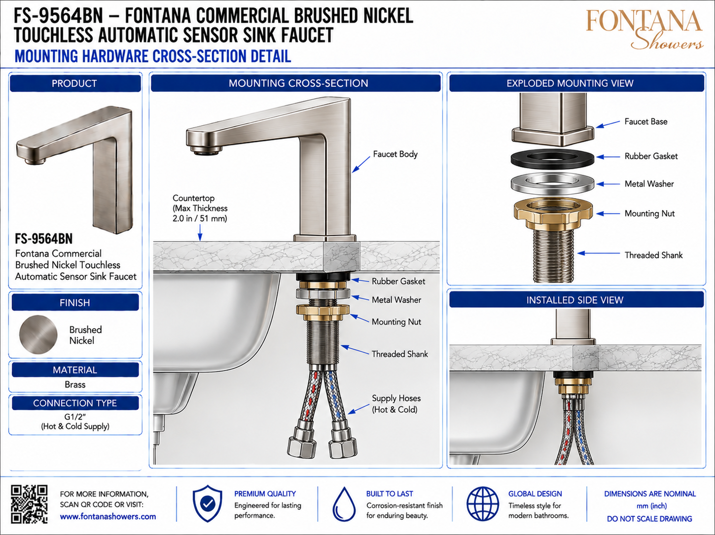
The FS-9564BN is designed with under-counter components that should remain accessible for inspection, troubleshooting, servicing and replacement. The service layout highlights the control box, solenoid valve, power source, supply lines and connection points, together with a recommended minimum service space for practical maintenance access.
- Model: FS-9564BN
- Fixture type: Touchless automatic sensor sink faucet
- Installation: Deck mounted / countertop mounted
- Finish: Brushed nickel
- Material: Brass
- Minimum service space: 305 mm (12 in.)
- Primary service component: Control box
- Water-control component: Solenoid valve
- Power source: AC adapter or optional battery pack
- Supply connections: G1/2 hot and cold
- Maintenance priority: Accessible, clean and dry under-counter area
Required Service & Maintenance Access Drawing Package
Each drawing should use a consistent component-identification system and clearly show the serviceable components, working clearances and access path beneath the countertop. The package should identify the control box, solenoid valve, power source, hot/cold supply connections, wiring and hoses, and should demonstrate how components can be reached, disconnected, serviced and reinstalled without removing the sink or countertop.
Under-Counter Service AreaShows the complete service zone beneath the lavatory, including the control box, solenoid valve, power source, hot and cold supply connections, and recommended working clearance.
Minimum Service ClearanceIdentifies a recommended minimum service space of 305 mm (12 in.) around the key under-counter components so technicians can inspect, disconnect and replace parts with practical access.
Control Box AccessShows the control box positioned where its connectors and enclosure remain accessible for inspection, troubleshooting, testing or replacement without disturbing unrelated plumbing.
Solenoid Valve AccessIdentifies the solenoid valve as a primary serviceable component. The valve should remain reachable so supply fittings and electrical connections can be serviced independently.
Power Source AccessShows the AC adapter or battery-pack location and emphasizes keeping the power source accessible for inspection, disconnection, battery replacement or component substitution.
Access ProcessIllustrates opening the cabinet to establish clear under-counter access before beginning service work. Cabinet hinges, shelves and stored items should not block the maintenance zone.
Service / Replacement ProcessShows components being disconnected for service or replacement. Shut off water and isolate power as required before loosening supply fittings or electrical connections.
Reinstallation ProcessAfter maintenance, reinstall the serviced component, confirm all plumbing and electrical connections are fully seated and restore the system only after inspection.
Maintenance InspectionPeriodically inspect the service area for leaks, loose fittings, cable damage, worn hoses, battery condition and general cleanliness before returning the fixture to normal operation.
Engineering note: Service-access drawings are provided for maintenance and coordination reference only. Maintain the recommended clear service area and verify the final control-box, solenoid-valve, power-source and supply-connection locations against the current FontanaShowers installation instructions and approved project submittal. Keep the under-counter service zone clean, dry and unobstructed. Do not scale dimensions from the drawing.
Service, Maintenance and Facility Coordination Considerations
Unobstructed AccessProvide a clear cabinet access path to all serviceable components and avoid placing shelves, stored items or fixed obstructions within the maintenance zone. Leak InspectionInspect supply hoses, fittings and the solenoid valve periodically for moisture, leakage or signs of wear, especially after servicing. Battery MaintenanceWhere battery power is used, position the battery pack where cells can be replaced easily without disturbing plumbing or control wiring. Electrical ProtectionKeep the control box, adapter and electrical connectors dry and away from potential leak paths or standing water inside the cabinet. Component ReinstallationAfter service, confirm all connectors, hose fittings and mounting points are secure before restoring power and water to the faucet system. Functional VerificationComplete several touchless activation cycles after maintenance and confirm reliable sensor response, proper valve operation and leak-free performance.
FontanaShowers Installation and Specification Resources
Professional Engineering and Accessibility References
Project verification: Service and maintenance access drawings are coordination tools and do not replace approved project submittals. The architect, plumbing engineer, electrical engineer, contractor, facility manager and qualified service technician should verify cabinet access, minimum service clearance, control-box location, solenoid-valve accessibility, power-source access, supply-hose routing, shutoff access and locally adopted codes before installation and throughout the fixture service life.
|
|
|