Fontana Commercial Touchless Faucets™ | Architectural and Engineering Resource
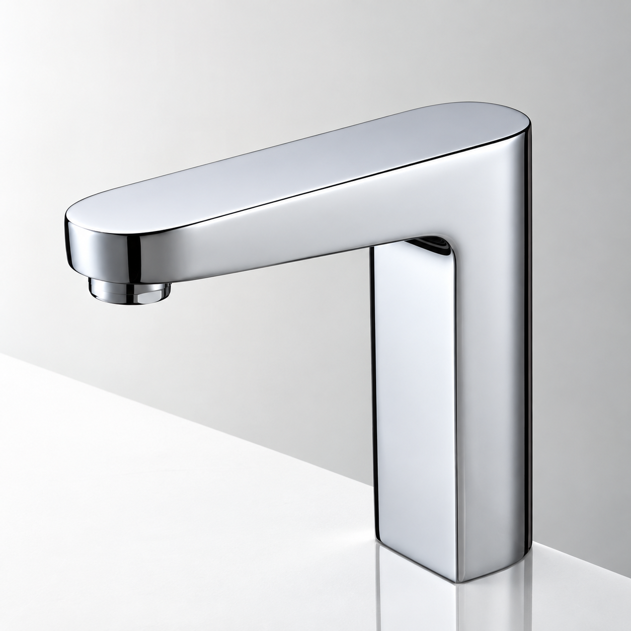
Fontana FS-9564BN Commercial Brushed Nickel Touchless Automatic Sensor Sink Faucet:
Solenoid Valve & Automatic Flow Diagram
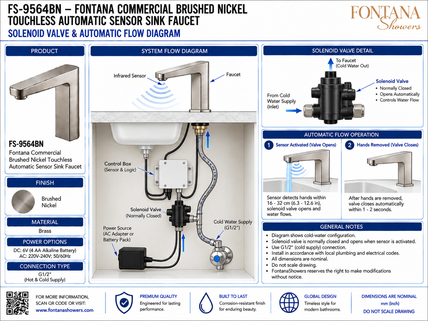
This solenoid-valve and automatic-flow resource is intended to support architects,
plumbing engineers, electrical engineers, contractors, installers and facility
managers coordinating the Fontana FS-9564BN commercial touchless automatic sensor
sink faucet. The drawing package communicates the relationship between the infrared
sensor, control box, power source, normally closed solenoid valve, G1/2 cold-water
supply and faucet outlet, together with the automatic opening and closing sequence.
Fontana FS-9564BN Automatic Water Flow Control System
The FS-9564BN uses an infrared sensor and control box to operate a normally
closed solenoid valve beneath the countertop. When hands enter the sensor zone,
the control system opens the valve and allows water to flow from the cold-water
supply to the faucet. Once hands are removed, the valve closes automatically.
- Model: FS-9564BN
- Fixture type: Touchless automatic sensor sink faucet
- Sensor type: Infrared (IR)
- Detection range: 16–32 cm (6.3–12.6 in.), adjustable
- Valve type: Normally closed solenoid valve
- Water configuration: Cold-water supply
- Cold-water connection: G1/2
- Control component: Control box / sensor logic
- Opening response: Less than 1 second
- Closing response: Approximately 1–2 seconds
- Battery option: DC 6V (4 AA alkaline batteries)
- AC option: 220–240V, 50/60Hz
Required Solenoid Valve & Automatic Flow Drawing Package
Each drawing should use a consistent component identification system and clearly
distinguish the sensor signal, electrical control path and water-flow path. The
package should identify the infrared sensor, control box, power source, solenoid
valve inlet and outlet, G1/2 cold-water connection and faucet outlet, together with
the automatic activation and shutoff sequence.
System Flow Diagram
Shows the complete operating relationship between the faucet sensor, control box, solenoid valve, power source and G1/2 cold-water supply. This view provides the main coordination reference for understanding automatic water flow.
Solenoid Valve Detail
Illustrates the normally closed solenoid valve with the cold-water inlet and outlet to the faucet. The valve opens only when energized by the control system and closes automatically when the activation signal ends.
Infrared Sensor Input
Shows the infrared sensor beneath the faucet spout detecting hands within the operating range and sending the activation signal to the control box.
Control Box Logic
Identifies the electronic control enclosure that receives sensor input, processes the command and energizes or de-energizes the solenoid valve.
Cold-Water Flow Path
Shows the water path from the G1/2 cold-water supply through the solenoid valve and upward to the faucet outlet. Hoses and fittings should remain accessible for inspection and service.
Sensor Activated — Valve Opens
When hands enter the adjustable 16–32 cm detection zone, the control box energizes the solenoid valve and water begins flowing through the faucet.
Hands Removed — Valve Closes
After hands leave the sensing field, the control system removes power from the solenoid valve and shuts off water automatically within approximately one to two seconds.
Power Source
Coordinates the illustrated AC-adapter or battery-pack option with the control box. Electrical connectors should remain dry, secure and accessible for service.
Functional Commissioning
Verify repeated sensor activation, correct valve opening and closing, stable water delivery and leak-free operation before placing the faucet into service.
Engineering note:
The automatic-flow diagram is a coordination reference and should not be scaled.
Verify solenoid-valve orientation, G1/2 connection compatibility, power-source
requirements, sensor range, control-box wiring and service access against the
current FontanaShowers installation instructions and approved project submittal.
Plumbing, Electrical and Sensor Coordination Considerations
Solenoid OrientationInstall the valve in the correct flow direction between the cold-water supply and faucet inlet to ensure proper automatic operation. Sensor AlignmentKeep the infrared sensing area unobstructed and verify the detection zone is centered over the usable basin area. Control WiringRoute sensor and valve wiring without pinching, excessive tension or contact with water-supply fittings and moving cabinet hardware. Power CoordinationCoordinate the AC-adapter or battery-pack option with the project power strategy and keep electrical connectors protected from moisture. Service AccessMaintain sufficient under-counter clearance to reach the solenoid valve, control box, power source and water connections for inspection and replacement. Leak & Function TestingAfter pressurizing the system, inspect all fittings for leaks and test several automatic activation cycles to verify consistent opening and shutoff behavior.
FontanaShowers Installation and Specification Resources
Professional Engineering and Accessibility References
Project verification:
Solenoid-valve and automatic-flow diagrams are coordination tools and do not replace
approved project submittals. The architect, plumbing engineer, electrical engineer,
contractor and qualified installer should verify valve orientation, G1/2 connection
compatibility, sensor range, control wiring, power-source requirements, service
access, accessibility criteria and locally adopted codes before installation and
commissioning.
|
|
|