Fontana Commercial Sensor Faucets™ | Architectural and Engineering Resource
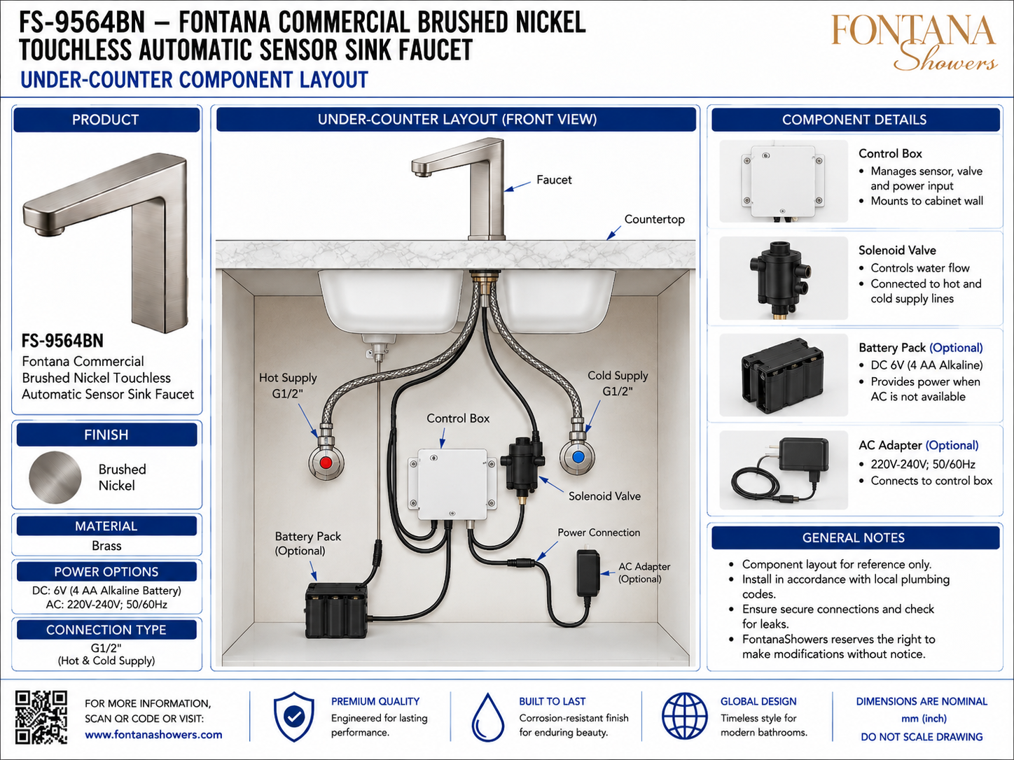
Fontana FS-9564BN Commercial Brushed Nickel Touchless Automatic Sensor Sink Faucet: Under-Counter Component Layout
This under-counter component layout resource is intended to support architects, plumbing engineers, electrical engineers, contractors, installers and facility managers coordinating the Fontana FS-9564BN commercial touchless automatic sensor sink faucet. The drawing package communicates the relationship between the faucet, G1/2 hot- and cold-water supplies, control box, solenoid valve, optional 6V battery pack, optional 220–240V AC adapter, power connection, cable routing and recommended service access beneath the countertop.
Fontana FS-9564BN Under-Counter Control and Power System
The FS-9564BN combines a deck-mounted touchless faucet with concealed electronic and plumbing components installed below the countertop. The layout supports clear separation of supply lines, sensor/control wiring and power components while preserving access for testing, maintenance and future replacement.
- Model: FS-9564BN
- Finish: Brushed nickel
- Material: Brass
- Fixture type: Touchless automatic sensor sink faucet
- Hot supply: G1/2
- Cold supply: G1/2
- Control component: Control box
- Water-control component: Solenoid valve
- Battery option: DC 6V (4 AA alkaline batteries)
- AC option: 220–240V, 50/60Hz
- Power connection: To control box
- Installation location: Under-counter / cabinet mounted
Required Under-Counter Component Layout Drawing Package
Each drawing should use a consistent component identification system and clearly distinguish plumbing, power and control connections. The package should identify the faucet connection, G1/2 hot and cold supplies, control box, solenoid valve, optional battery pack, optional AC adapter and associated cable routing. Components should be positioned for secure mounting, clear access and practical maintenance.
Under-Counter System Overview
Shows the complete relationship between the faucet, countertop, hot and cold supplies, control box, solenoid valve, optional battery pack and optional AC adapter. This view provides the primary reference for cabinet coordination and installation planning.
Control Box
Identifies the central control enclosure that manages sensor input, valve operation and power distribution. Mount the box securely to the cabinet wall where its connectors remain visible and accessible.
Solenoid Valve
Shows the electrically actuated valve that controls water flow to the faucet. The valve should remain accessible for inspection, cleaning and replacement without removing the faucet from the countertop.
Hot & Cold Supply Connections
Shows separate G1/2 hot and cold water supplies routed to the under-counter system. Supply hoses should be arranged without kinks and remain clear of electrical connectors and moving cabinet hardware.
Optional Battery Pack
Identifies the 6V battery option using four AA alkaline batteries. The battery pack provides power where AC supply is unavailable and should remain easy to reach for battery replacement.
Optional AC Adapter
Shows the optional 220–240V, 50/60Hz AC adapter connected to the control box. Position the adapter and cable so they remain protected from leaks and accessible for service.
Power Connection
Defines the electrical connection between the selected power source and the control box. Keep connectors dry, fully seated and routed away from sharp edges or water-supply fittings.
Cable Routing
Route sensor and power cables in smooth paths without pinching, excessive tension or contact with hot surfaces. Secure loose wiring to cabinet surfaces where appropriate.
Service & Maintenance Access
Maintain adequate clear space around the control box, solenoid valve, power components and supply connections so components can be inspected, disconnected and replaced without disturbing unrelated plumbing.
Engineering note: The component layout is a coordination reference and should not be scaled. Final positions should be verified against cabinet dimensions, drain geometry, supply-hose reach, electrical requirements and the current FontanaShowers installation instructions. Keep all electrical components protected from moisture and maintain unobstructed service access.
Plumbing, Electrical and Service Coordination Considerations
Component Mounting
Secure the control box, solenoid valve and power components to stable cabinet surfaces where they will not shift during normal use or maintenance.
Supply-Line Routing
Keep the hot and cold G1/2 supply hoses clear of the drain assembly, cabinet hinges and electrical connectors while maintaining generous bend radii.
Power Source Selection
Coordinate either the optional 6V battery supply or optional 220–240V AC adapter according to the project power strategy and installation requirements.
Moisture Protection
Locate the control box, power adapter and electrical connectors away from likely leak paths and areas subject to direct water exposure.
Maintenance Clearance
Provide enough cabinet space to remove the battery pack, access the solenoid valve and disconnect control-box wiring without removing the sink or countertop.
Commissioning
After installation, verify secure plumbing connections, correct power operation, reliable sensor response and leak-free solenoid-valve performance.
FontanaShowers Installation and Specification Resources
Professional Engineering and Accessibility References
Project verification: Under-counter component layouts are coordination tools and do not replace approved project submittals. The architect, plumbing engineer, electrical engineer, contractor and licensed installer should verify control-box placement, solenoid location, G1/2 supply connections, power-source requirements, cable routing, moisture protection, cabinet service access, accessibility criteria and locally adopted codes before installation.
|
|
|