Fontana Commercial Sensor Faucets™ | Architectural and Engineering Resource
Fontana FS-354AQ-DP Antique Commercial Automatic Sensor Faucet:
Solenoid Valve and Control-Box Installation Layout
This solenoid-valve and control-box installation resource supports architects,
plumbing engineers, specifiers, contractors, installers and facility teams
coordinating the below-counter components of the Fontana FS-354AQ-DP
commercial automatic sensor faucet. The layout identifies the vertically
mounted solenoid valve, electronic control box, sensor cable, faucet water
connection, building water inlet, optional AC power adapter, mounting
clearances and minimum service-access zone required for installation,
inspection and component replacement.
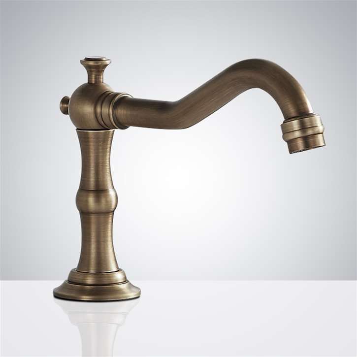
FS-354AQ-DP Sensor Faucet Control Assembly
The FS-354AQ-DP installation combines a deck-mounted automatic
sensor faucet with an under-counter solenoid valve and separate
electronic control box. The faucet sensor cable passes below the
mounting surface to the electronic controller, while the water
supply connects through the solenoid valve before continuing to
the faucet. The solenoid assembly is installed vertically with
the coil positioned upward, and all serviceable components should
remain accessible after the lavatory installation is complete.
-
Model:
FS-354AQ-DP
-
Fixture type:
Commercial automatic sensor faucet
-
Installation:
Deck mounted
-
Finish:
Antique brass
-
Construction:
Solid brass
-
Solenoid installation:
Vertical mount with coil up
-
Control-box installation:
Vertical wall / cabinet mounting below counter
-
Water inlet:
1/2 in NPT (G1/2)
-
Water outlet to faucet:
1/2 in NPT (G1/2)
-
Sensor cable:
Pre-attached and waterproof
-
Inlet water pressure:
20–80 PSI (138–552 kPa)
-
Water temperature:
1–60°C (34–140°F)
-
Water flow:
1.2 GPM (4.54 L/min) at 60 PSI
-
Sensor range:
Adjustable 16–32 cm (6.30–12.60 in)
-
Power:
DC 6V (4 × AA) or AC 110–220V, 50/60Hz
-
Minimum service-access zone:
300 mm (11.81 in)
Required Solenoid Valve & Control-Box Installation Drawing Package
The installation drawing should identify the relationship between the
deck-mounted faucet and all below-counter control components. The
solenoid valve should be shown vertically with its coil upward, the
electronic control box should remain accessible for electrical service,
and the pre-attached sensor cable should route from the faucet to the
controller without strain. Water inlet and outlet connections, power
routing, mounting-surface limitations and required service clearances
should be coordinated before final installation.
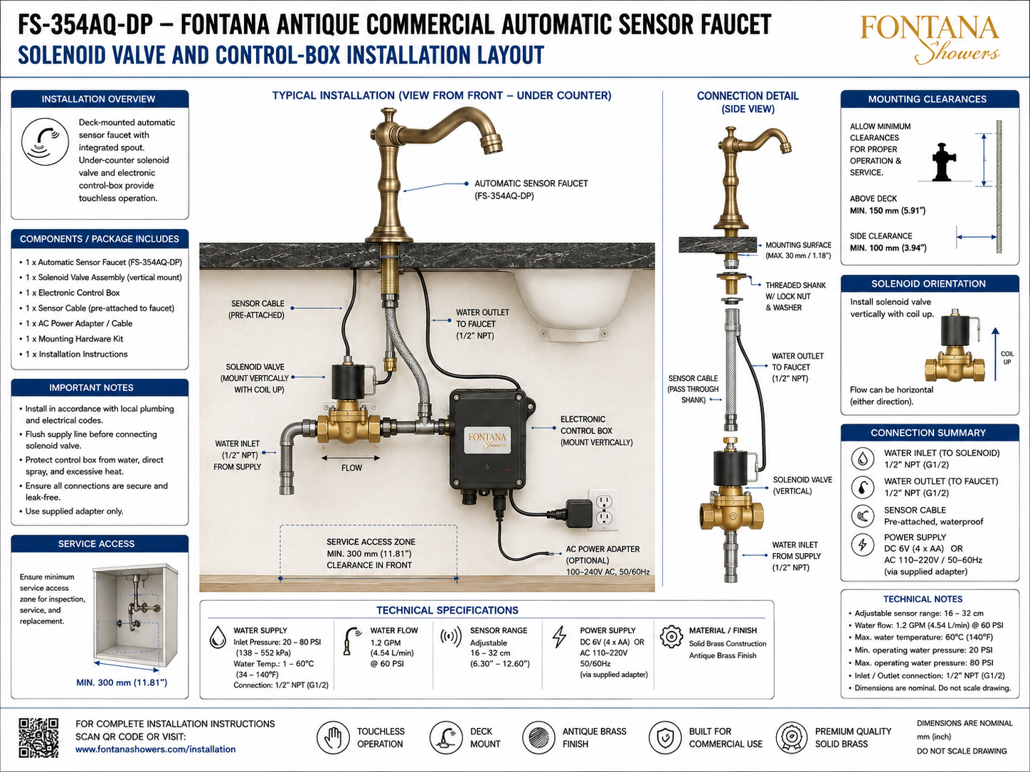
Solenoid Valve & Control-Box Installation Layout
Shows the complete under-counter arrangement serving the
FS-354AQ-DP automatic faucet, including the faucet body,
pre-attached sensor cable, vertical solenoid valve, electronic
control box, building water inlet, faucet water outlet,
optional AC adapter and required service-access zone.
Typical Under-Counter Installation
The front installation view establishes the relative positions
of the solenoid valve, electronic control box and associated
water and electrical connections below the countertop.
Components should be arranged so inspection and replacement
can occur without removing the faucet or lavatory.
Vertical Solenoid Orientation
The solenoid-valve assembly is installed vertically with
the electrical coil positioned upward. The diagram permits
horizontal water flow through the valve in either direction
while maintaining the specified vertical coil orientation.
Electronic Control-Box Position
The electronic control box is mounted vertically below
the countertop in a protected and accessible location.
Keep the enclosure away from direct water spray, excessive
heat and conditions that could interfere with electrical
connections or routine servicing.
Water Inlet to Solenoid
The building water supply connects to the solenoid-valve
inlet using the identified 1/2 in NPT (G1/2) connection.
The supply line should be flushed before connection so
debris does not enter the solenoid assembly.
Water Outlet to Faucet
The controlled water outlet from the solenoid assembly
connects to the faucet through the 1/2 in NPT (G1/2)
faucet-side connection. The outlet line should remain free
of kinks, excessive bends and mechanical strain.
Sensor-Cable Routing
The waterproof sensor cable is pre-attached to the faucet
and passes below the mounting surface through the faucet
assembly. Route the cable to the electronic control box
without pinching, stretching or placing it against sharp edges.
Power-Supply Connection
The control system supports a DC 6V battery configuration
using four AA batteries or an AC 110–220V, 50/60Hz
connection through the supplied power adapter. Electrical
connections should remain protected and serviceable.
Service-Access Zone
The installation layout identifies a minimum 300 mm
(11.81 in) clear service zone in front of the below-counter
components. Preserve this access for inspection, electrical
testing, solenoid servicing and component replacement.
Engineering note:
The solenoid valve and control-box installation drawing is a
coordination resource and should not be scaled. Maintain the
solenoid vertically with the coil upward, protect the control box
from water and excessive heat, preserve the identified service
clearances and verify all plumbing and electrical connections
before placing the faucet into service.
Installation & Mounting Coordination Considerations
Above-Deck Clearance
The diagram identifies a minimum 150 mm (5.91 in)
above-deck clearance for proper faucet installation,
operation and access around the fixture.
Side Clearance
Maintain a minimum 100 mm (3.94 in) side clearance
from adjacent vertical construction where indicated so
the faucet and related components remain accessible.
Mounting-Surface Thickness
The connection-detail drawing identifies a maximum
mounting-surface thickness of 30 mm (1.18 in).
Verify countertop thickness before installing the
threaded faucet shank, lock nut and washer.
Solenoid Position
Mount the solenoid valve vertically with its coil upward.
Do not rotate the assembly into an orientation that places
the coil below or horizontally beside the valve body.
Control-Box Protection
Install the electronic control box in a dry under-counter
location protected from direct spray, standing water and
excessive heat while retaining access to its wiring and
power connections.
Service Accessibility
Provide at least 300 mm (11.81 in) of clear working
space in front of the under-counter components so the
solenoid, controller, connections and power components
can be inspected and serviced.
Solenoid & Control-System Components
Technical Installation Requirements
-
Water-Supply Operating Range
The installation diagram identifies an inlet-pressure range
of 20–80 PSI (138–552 kPa), with a water-temperature
range of 1–60°C (34–140°F).
-
Water-Flow Performance
The stated faucet flow is 1.2 GPM (4.54 L/min) at
60 PSI.
-
Adjustable Sensor Range
The automatic sensor has an adjustable sensing range of
16–32 cm (6.30–12.60 in).
-
Power Configuration
The control system supports DC 6V power using four AA
batteries or AC 110–220V at 50/60Hz through the
supplied adapter.
-
Inlet & Outlet Connections
Both the water inlet to the solenoid and water outlet
toward the faucet are identified as 1/2 in NPT
(G1/2) connections.
-
Solenoid Orientation
Install the solenoid valve vertically with the coil upward.
The diagram indicates that water flow through the valve
can be horizontal in either direction.
-
Pre-Installation Flushing
Flush the building supply line before connecting the
solenoid valve to reduce the possibility of debris entering
the valve and affecting operation.
-
Leak Verification
Ensure plumbing connections are secure and leak-free
before commissioning the automatic faucet system.
Project verification:
The solenoid valve and control-box installation layout is a
coordination resource and should not be scaled. Before installation,
verify the 1/2 in NPT (G1/2) inlet and outlet connections,
20–80 PSI operating-pressure range, 1–60°C water-temperature range,
1.2 GPM flow at 60 PSI, 16–32 cm adjustable sensor range,
30 mm maximum mounting-surface thickness, 150 mm above-deck
clearance, 100 mm side clearance, 300 mm minimum service-access
zone, vertical solenoid orientation, sensor-cable routing, electronic
control-box location and selected DC or AC power arrangement against
the approved project installation requirements.
|
|
|