Fontana Commercial Sensor Faucets™ | Architectural and Engineering Resource
Fontana FS-354AQ-DP Antique Commercial Automatic Sensor Faucet:
Water Supply & Plumbing Connection Diagram
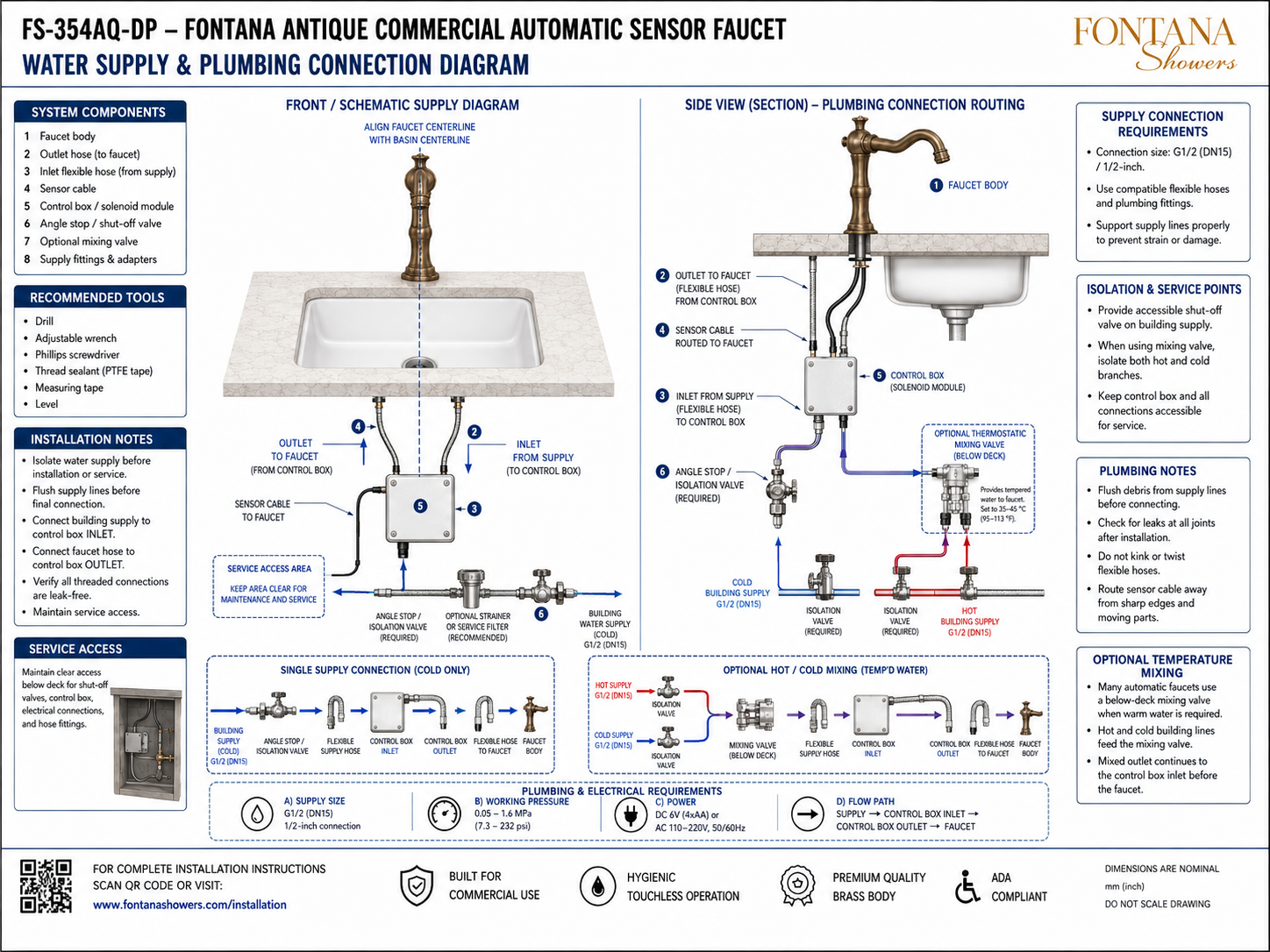
This water-supply and plumbing-connection resource supports architects,
plumbing engineers, specifiers, contractors, installers and facility teams
coordinating the Fontana FS-354AQ-DP commercial automatic sensor faucet.
The diagram establishes the complete hydraulic path from the building water
supply through the isolation valve, flexible supply hose and control-box
inlet to the faucet outlet connection. It also illustrates the optional
hot-and-cold mixing arrangement, sensor-cable routing, service-access
requirements and principal plumbing and electrical connection criteria.
Fontana FS-354AQ-DP Water-Supply Connection System
The Fontana FS-354AQ-DP uses a below-deck water-control arrangement
in which the building supply is connected through an accessible
isolation valve and flexible inlet hose to the electronic control
box / solenoid module. From the control-box outlet, a second flexible
hose supplies the faucet body above the deck. Where tempered water
is required, an optional below-deck mixing valve can combine the
hot and cold building supplies before the mixed-water line enters
the control assembly.
-
Model:
FS-354AQ-DP
-
Fixture type:
Commercial automatic sensor faucet
-
Installation:
Deck mounted
-
Primary supply connection:
G1/2 in (DN15)
-
Connection equivalent:
1/2-inch connection
-
Primary hydraulic configuration:
Single building water supply to control-box inlet
-
Faucet connection:
Flexible outlet hose from control box to faucet body
-
Isolation:
Accessible angle stop / shut-off valve required
-
Optional water treatment:
Strainer or service filter
-
Optional temperature control:
Below-deck hot/cold mixing valve
-
Working pressure:
0.05–1.6 MPa (7.3–232 psi)
-
Power:
DC 6V (4 × AA) or AC 110–220V, 50/60Hz
-
Control component:
Control box / solenoid module
-
Sensor connection:
Sensor cable routed from faucet to control box
-
Service requirement:
Keep control box, isolation valves and hose connections accessible
Required Water-Supply & Plumbing Connection Drawing Package
The plumbing drawing should clearly establish the complete water path
from the building supply to the faucet and identify every accessible
service and control component. The connection sequence should distinguish
the building supply, isolation valve, optional strainer, flexible inlet
hose, control-box inlet, solenoid-controlled outlet, flexible faucet
hose and faucet body. Where tempered water is required, the hot and cold
branches and optional mixing valve should be shown as a separate
configuration before the mixed-water supply enters the control box.
Water Supply & Plumbing Connection Diagram
Shows the complete hydraulic arrangement serving the
FS-354AQ-DP, from the building water supply through the
isolation and control components to the faucet body.
The drawing also identifies hose routing, sensor connection,
service clearances and the optional hot/cold mixing configuration.
Building Water Supply
The primary supply arrangement begins with a G1/2 in
(DN15) building water connection. The supply piping should
terminate at an accessible isolation point before the flexible
hose connects the building system to the electronic control module.
Angle Stop / Isolation Valve
An accessible angle stop or shut-off valve is required between
the building supply and faucet-control assembly. The valve
provides a local means of isolating the faucet during installation,
commissioning, inspection or service.
Flexible Supply Hose
A compatible flexible inlet hose connects the isolated
building water supply to the control-box inlet. The hose
should be routed without kinking, twisting, excessive tension
or contact with sharp edges and moving components.
Control Box / Solenoid Module
The below-deck control box contains the water-control
assembly serving the automatic faucet. Water enters through
the designated inlet and exits through the controlled outlet
after automatic activation commands are received from the
faucet sensor.
Control-Box Outlet to Faucet
The control-box outlet connects to the faucet body through
a separate flexible hose. This establishes the final controlled
water path from the solenoid module to the above-deck faucet
and terminal outlet.
Sensor Cable Routing
The faucet sensor cable is routed below the countertop to
the electronic control box. Maintain separation from sharp
edges and moving components and provide sufficient slack
for installation and service without placing strain on
the electrical connectors.
Optional Hot / Cold Mixing
Where tempered water is required, independent hot and cold
G1/2 (DN15) building supplies can feed an optional below-deck
mixing valve. The mixed-water outlet then continues through
the flexible supply hose to the control-box inlet before
flowing to the faucet.
Working Pressure & Power
The plumbing and electrical requirements shown identify
a working-pressure range of 0.05–1.6 MPa (7.3–232 psi)
and power options of DC 6V using four AA batteries or
AC 110–220V at 50/60Hz.
Engineering note:
The plumbing connection drawing is schematic and should not be scaled.
Verify the G1/2 / DN15 building connection, available working pressure,
isolation-valve locations, flexible-hose compatibility, control-box
inlet and outlet orientation, optional mixing-valve configuration,
sensor-cable routing and service clearances before final installation.
Plumbing Coordination & Service Considerations
Supply Isolation
Provide an accessible shut-off valve on the building water
supply so the faucet and control system can be isolated
without shutting down unrelated plumbing fixtures.
Supply-Line Flushing
Flush debris from the building supply piping before making
the final faucet connections. Keep contaminants from entering
the flexible hoses, control-box waterway or solenoid assembly.
Hose Routing
Route the inlet and outlet flexible hoses without kinks,
twists or excessive bends. Support the lines so their weight
or movement does not impose unnecessary strain on fittings
or control-box connections.
Control-Box Accessibility
Locate the control / solenoid module where its water,
electrical and sensor connections remain accessible
after the lavatory, countertop and surrounding casework
have been completed.
Hot & Cold Isolation
When an optional mixing valve is used, provide independent
isolation for both the hot and cold branches so either
supply can be serviced without disturbing the permanent
building distribution system.
Leak Testing
After installation, inspect all threaded fittings,
flexible-hose connections, control-box connections and
optional mixing-valve joints for leakage before the
installation is placed into regular service.
Water-Supply Components & Connection Sequence
Plumbing Configuration Requirements
-
Single Cold-Water Supply
The basic configuration routes the G1/2 (DN15) building
supply through an angle stop / isolation valve and flexible
supply hose to the control-box inlet. Water then leaves the
control-box outlet through a second flexible hose to the faucet.
-
Optional Tempered-Water Supply
Where mixed water is required, separately isolated G1/2
(DN15) hot and cold building supplies feed a below-deck
mixing valve. Its mixed outlet then feeds the faucet-control
assembly.
-
Optional Strainer / Service Filter
The schematic identifies an optional strainer or service
filter in the supply path. Where incorporated, maintain
adequate clearance so the component can be inspected or
serviced without removing surrounding plumbing.
-
Service Access Area
Keep the under-counter area around the control box,
shut-off valves, electrical connections and flexible
hose fittings clear for commissioning, maintenance and
future component replacement.
-
Flow Path
The normal hydraulic sequence is:
building supply → isolation valve → flexible inlet hose →
control-box inlet → control-box outlet → flexible outlet hose →
faucet body.
Project verification:
The water-supply and plumbing-connection diagram is a coordination
resource and should not be scaled. Before installation, verify the
G1/2 / DN15 supply connection, available 0.05–1.6 MPa
(7.3–232 psi) working pressure, isolation-valve locations,
flexible-hose compatibility, control-box inlet and outlet orientation,
sensor-cable routing, power configuration, optional strainer,
optional hot/cold mixing arrangement and required under-deck service
access against the approved product documentation and actual
project plumbing conditions.
|
|
|