Fontana Touchless Faucets™ | Architectural and Engineering Resource
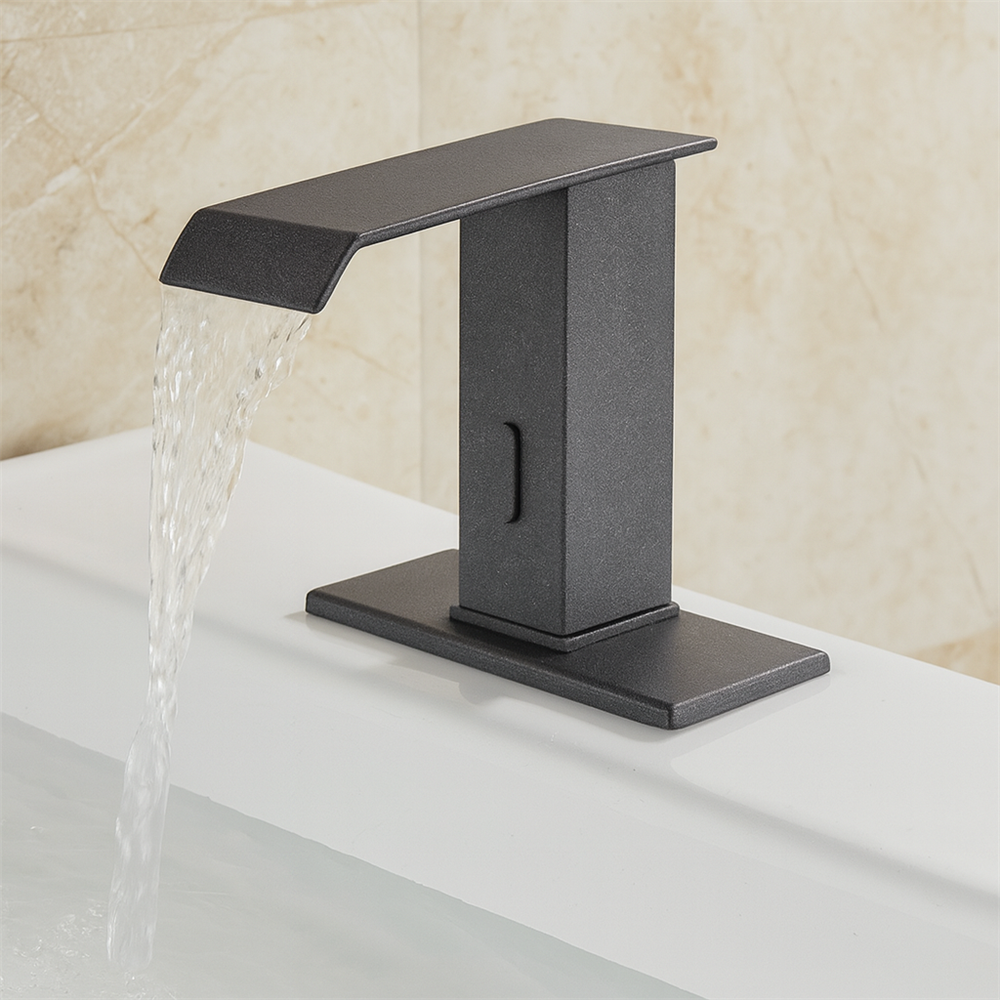
Fontana Lymora FS9099BGR Black Granite Automatic Motion Sensor Faucet:
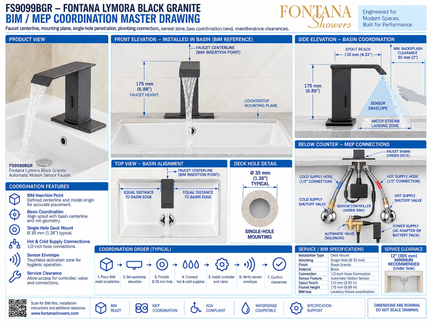
BIM / MEP Coordination Master Drawing
This BIM / MEP coordination resource is intended to support architects, plumbing
engineers, BIM coordinators, MEP designers, contractors, millwork teams and
installers coordinating the Fontana Lymora FS9099BGR Black Granite automatic
motion-sensor faucet. The drawing package consolidates the BIM insertion point,
countertop mounting plane, single-hole penetration, hot and cold water
connections, sensor envelope, basin coordination zone, controller / solenoid
service area and required maintenance clearances.
Fontana Lymora FS9099BGR BIM / MEP Coordination Reference
The FS9099BGR should be coordinated as a complete lavatory fixture assembly,
using the faucet centerline as the BIM insertion point and the finished
countertop as the primary mounting plane. The model should also account for the
single-hole penetration, hot / cold connections, infrared sensing zone, basin
landing area, under-deck controller / solenoid assembly and service clearance.
- Model: FS9099BGR
- Installation type: Deck mount
- Mounting: Single hole
- Finish: Black Granite
- Material: Brass
- Valve core: Ceramic
- Sensor feature: Automatic motion sensor
- Connection: 1/2-inch hose connection
- Spout reach: 110 mm (4.33 in.)
- Overall faucet height: Approximately 175 mm (6.89 in.)
- Typical mounting penetration: Ø35 mm (1.38 in.)
- Recommended rear clearance: Approximately 50 mm (2 in.) minimum
- Recommended service clearance: 12 in. (305 mm) minimum
Required BIM / MEP Coordination Drawing Package
Each coordination drawing should use a consistent project origin, finished
countertop datum and faucet / basin centerline. The package should clearly
identify the BIM insertion point, mounting plane, single-hole penetration,
supply connections, sensor activation envelope, basin landing zone, controller
and solenoid service zone, waste-line relationship and maintenance clearance.
BIM / MEP Coordination Master Drawing
Provides the consolidated fixture-coordination view for the FS9099BGR, integrating mounting, plumbing, controls, sensor coverage, basin alignment and service-access requirements.
BIM Insertion Point
Uses the faucet centerline as the primary model insertion point so architectural, plumbing and millwork documents share a consistent fixture origin.
Countertop Mounting Plane
Establishes the finished countertop surface as the principal vertical datum for faucet placement, mounting hardware, basin coordination and below-deck component positioning.
Single-Hole Penetration
Identifies a typical Ø35 mm (1.38 in.) deck penetration aligned with the faucet and basin centerlines. Final hole size should be verified before fabrication.
Hot & Cold Connections
Coordinates the 1/2-inch hot-water connection on the left and cold-water connection on the right, with accessible shutoff valves beneath the countertop.
Controller / Solenoid Zone
Reserves under-counter space for the electronic controller, automatic valve / solenoid, power supply, sensor cable and water connections while maintaining service access.
Sensor Activation Envelope
Shows the touchless sensing zone extending forward from the faucet body. The model should keep nearby objects and reflective surfaces clear of this activation path.
Basin Coordination Zone
Aligns the faucet centerline and water-stream landing zone with the usable bowl area so the waterfall discharge remains inside the basin and near the drain zone.
Service / Maintenance Clearance
Maintains a recommended 12 in. (305 mm) minimum under-counter service zone for shutoff valves, hoses, controller, solenoid, faucet shank and mounting hardware.
Engineering note:
The dimensions, service zones and BIM relationships shown are nominal coordination
references. Final faucet insertion point, countertop penetration, supply routing,
basin location, controller placement, sensor envelope, backsplash clearance and
maintenance access should be verified against the approved Fontana Lymora
FS9099BGR installation documentation and the actual project architectural / MEP
model before fabrication or installation.
Architectural, Plumbing and BIM Coordination Considerations
Centerline Control
Align the faucet insertion point with the basin centerline so the sensor field and waterfall landing zone remain coordinated with the bowl.
Countertop Fabrication
Verify finished deck elevation, thickness and mounting-hole location before releasing the countertop for fabrication.
Supply Routing
Keep hot supply on the left and cold supply on the right, preserve shutoff access and route hoses clear of the drain and cabinet hardware.
Control-System Space
Allocate enough under-deck space for the controller, solenoid, power connection and service wiring without conflict with the waste system.
Sensor & Basin Zone
Keep the intended hand-activation envelope and waterfall stream inside the basin footprint and clear of reflective or obstructive objects.
Maintenance Clearance
Preserve the recommended 12-inch service zone so control components, shutoffs and mounting hardware remain accessible after millwork completion.
FontanaShowers BIM and Installation Resources
Professional Engineering and BIM References
Project verification:
BIM / MEP coordination drawings are design and coordination tools and do not
replace approved project submittals. The architect, plumbing engineer, BIM
coordinator, MEP designer, millwork fabricator, contractor and licensed installer
should verify insertion point, countertop penetration, supply routing, controller
and solenoid location, sensor zone, basin alignment, waste-line clearance,
maintenance access and locally adopted plumbing requirements before fabrication
or installation.
|
|
|