Fontana Touchless Faucets™ | Architectural and Engineering Resource
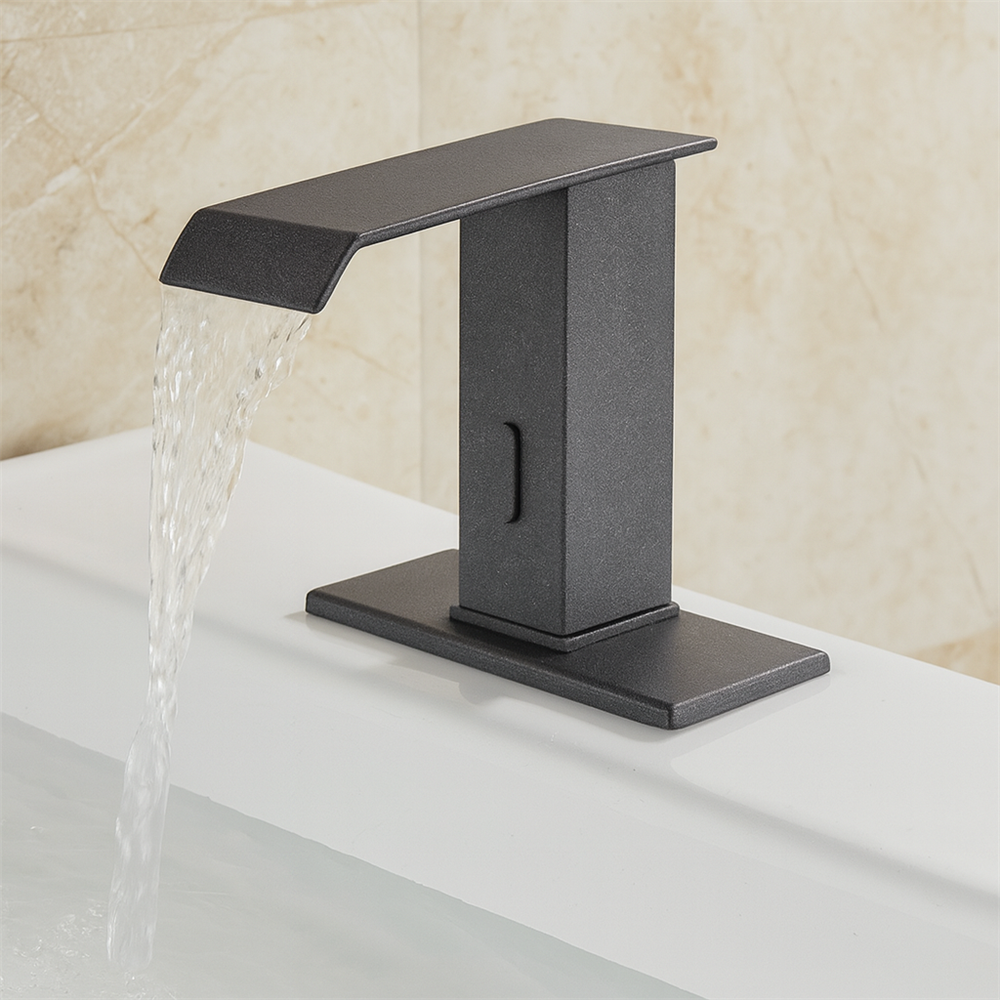
Fontana Lymora FS9099BGR Black Granite Automatic Motion Sensor Faucet:
Faucet Exploded Assembly Drawing
This exploded-assembly resource is intended to support plumbing engineers,
contractors, installers, maintenance personnel and facility managers reviewing
the Fontana Lymora FS9099BGR Black Granite automatic motion-sensor faucet.
The drawing package communicates the exterior body, brass structural core,
infrared sensor module, ceramic valve core, seals and O-rings, deck-mounting
hardware, supply hoses, connector fittings, outlet assembly and serviceable
component order.
Fontana Lymora FS9099BGR Serviceable Faucet Assembly
The FS9099BGR combines a Black Granite exterior shell with a brass structural
body, ceramic valve core, automatic infrared sensor module and single-hole
deck-mounting hardware. The exploded drawing shows how the serviceable
components fit together and how the hot / cold hoses, control lead and outlet
assembly connect to the faucet body.
- Model: FS9099BGR
- Material: Brass structural body
- Finish: Black Granite
- Valve core: Ceramic cartridge
- Sensor: Automatic infrared motion sensor
- Installation: Single-hole deck mount
- Connection: 1/2-inch hose connection
- Spout reach: 110 mm (4.33 in.)
- Spout height: 110 mm (4.33 in.)
- Overall faucet height: Approximately 175 mm (6.89 in.)
- Serviceable parts: Sensor, cartridge, seals, outlet and mounting components
Required Faucet Exploded Assembly Drawing Package
Each assembly drawing should use a consistent component-identification scheme
and clearly show the relationship between the exterior body, structural brass
core, sensor module, ceramic valve core, seals, mounting hardware, electrical
lead, supply hoses and outlet parts. Service sequences should preserve component
order and maintain access for inspection, replacement and reassembly.
Faucet Exploded Assembly Drawing
Shows the complete serviceable assembly, including the Black Granite exterior shell, brass structural body, infrared sensor module, ceramic valve core, internal seals, faucet shank, deck-mounting hardware, supply hoses, connector fittings and outlet / aerator components.
Exploded View — Primary Assembly
Separates the faucet into its principal construction groups so the relationship between the exterior shell, internal brass body, sensor module, cartridge, seals, mounting hardware and water connections can be reviewed during installation or service.
Black Granite Exterior Body
Identifies the finished faucet shell and spout cover that provide the architectural appearance while enclosing the structural and control components. Protect the finish from scratching and abrasive tools during service.
Brass Structural Body
Shows the internal brass main body that supports the water passages, sensor module, ceramic valve core and deck-mount connection and provides the primary mechanical structure of the faucet.
Infrared Sensor Module
Positions the automatic sensor behind the front-facing sensor window. Correct alignment between the sensor module and exterior opening is important for reliable touchless activation.
Ceramic Valve Core & Internal Seals
Shows the ceramic cartridge together with the O-rings, seals and gaskets that control water flow and maintain watertight internal joints. Inspect these parts for wear, debris or damage during maintenance.
Deck Mounting Hardware
Illustrates the faucet shank, deck gasket, mounting plate / washer and locknut used to secure the faucet through the single countertop penetration. Tighten hardware evenly without stressing the countertop.
Hot / Cold Hoses & Connectors
Identifies the separate hot and cold supply hoses and 1/2-inch connector fittings below the faucet. Hoses should be routed without kinks or excessive twisting and remain accessible for service.
Section View & Component Order
Shows how the internal components align within the finished faucet body and summarizes the typical assembly order from exterior shell through the structural body, sensor, ceramic valve, seals, mounting hardware and hose connectors.
Engineering note:
The exploded assembly shown is a coordination and service reference. Final part
configuration, cartridge design, sensor-module arrangement, seal sequence,
mounting hardware, hose connections and service procedure should be verified
against the approved Fontana Lymora FS9099BGR product documentation before
disassembly, repair or component replacement.
Assembly, Service and Maintenance Considerations
Finish Protection
Protect the Black Granite exterior during installation and service, and avoid abrasive cleaners, metal tools or harsh chemicals on exposed finished surfaces.
Sensor Alignment
Maintain correct alignment between the infrared sensor module and front sensor window so the sensing path remains unobstructed after reassembly.
Seal Inspection
Inspect O-rings, gaskets and internal seals during servicing, replace damaged components and confirm that all seals are correctly seated before pressurizing the faucet.
Mounting Hardware
Tighten the mounting plate and locknut evenly so the faucet remains stable without distorting the deck or over-compressing the mounting gasket.
Hose Routing
Keep hot and cold hoses free of kinks, twisting and sharp bends, and leave enough slack to permit inspection, disconnection and future replacement.
Post-Service Testing
After reassembly, check for leaks, verify sensor activation and automatic shutoff, and confirm that the outlet produces an even, unobstructed waterfall stream.
FontanaShowers Installation and Specification Resources
Professional Engineering and Accessibility References
Project verification:
Exploded-assembly drawings are coordination and service tools and do not replace
approved product documentation. The plumbing engineer, contractor, installer
and maintenance provider should verify component order, cartridge type, seal
condition, sensor alignment, hose connections, mounting hardware, electrical
leads, service procedures and locally adopted plumbing requirements before
disassembly or repair.
|
|
|