Fontana Touchless Faucets™ | Architectural and Engineering Resource
Fontana Lymora FS9099BGR Black Granite Automatic Motion Sensor Faucet:
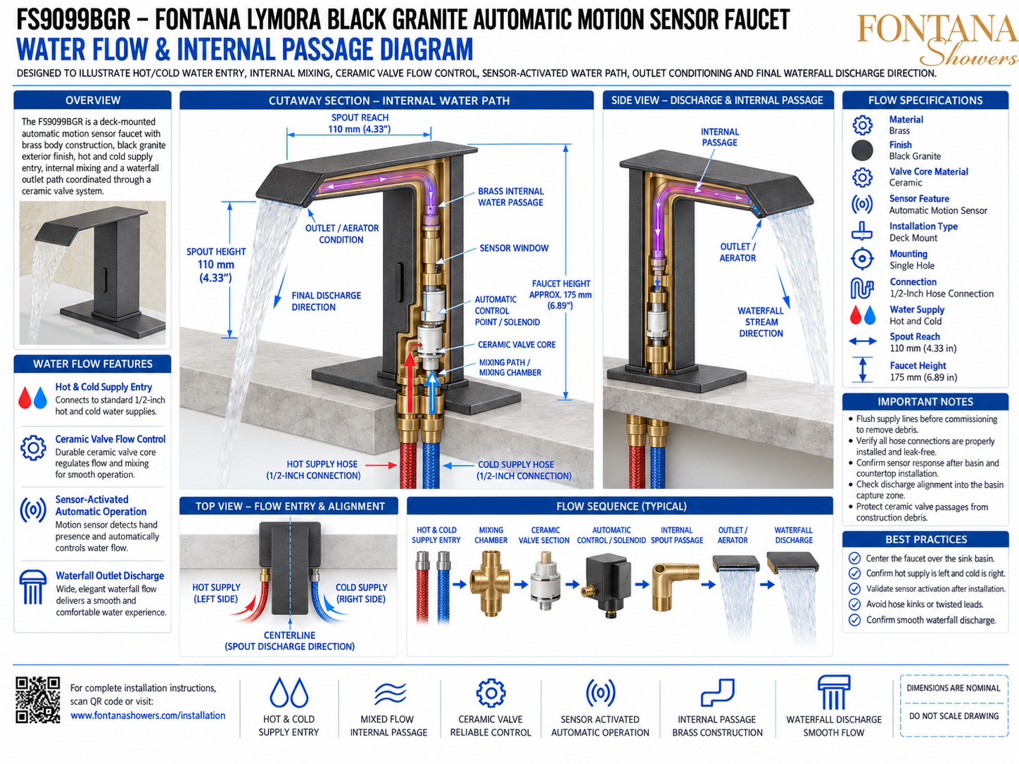
Water Flow & Internal Passage Diagram
This water-flow resource is intended to support plumbing engineers, contractors,
installers, maintenance personnel and facility managers reviewing the Fontana
Lymora FS9099BGR Black Granite automatic motion-sensor faucet. The drawing package
communicates hot- and cold-water entry, the internal mixing chamber, ceramic valve
flow control, sensor-activated automatic control, brass internal water passage,
outlet conditioning and final waterfall discharge direction.
Fontana Lymora FS9099BGR Internal Water-Flow System
The FS9099BGR receives separate hot- and cold-water supplies through 1/2-inch
connections, combines them within the lower mixing section and controls the flow
through a ceramic valve and sensor-activated automatic control. Mixed water then
travels through the brass internal passage to the outlet / aerator, where it is
conditioned for the final waterfall discharge.
- Model: FS9099BGR
- Material: Brass
- Finish: Black Granite
- Valve core: Ceramic
- Sensor feature: Automatic motion sensor
- Installation: Single-hole deck mount
- Connection: 1/2-inch hose connection
- Water supply: Hot and cold
- Spout reach: 110 mm (4.33 in.)
- Spout height: 110 mm (4.33 in.)
- Overall faucet height: Approximately 175 mm (6.89 in.)
- Discharge: Waterfall flow
Required Water Flow and Internal Passage Drawing Package
Each internal-flow drawing should use a consistent flow-direction convention and
component-identification scheme. The package should clearly identify hot and cold
supply entry, mixing chamber, ceramic valve core, automatic control / solenoid,
vertical and horizontal brass passages, outlet conditioning and final discharge
direction for installation, commissioning and service reference.
Water Flow & Internal Passage Diagram
Shows the complete hydraulic path from hot and cold supply entry through internal mixing, ceramic valve control, automatic actuation, brass spout passage, outlet conditioning and final waterfall discharge.
Cutaway Section — Internal Water Path
Exposes the internal flow route through the faucet body, showing the lower mixing area, ceramic valve, automatic control section, vertical passage and horizontal spout channel.
Hot & Cold Supply Entry
Identifies the hot-water connection on the left and cold-water connection on the right, each using a nominal 1/2-inch hose connection.
Mixing Path / Chamber
Shows the point where hot and cold supplies combine before entering the ceramic valve section. This area should remain free of construction debris and mineral buildup.
Ceramic Valve Flow Control
Identifies the ceramic valve core that regulates internal water flow and supports smooth operation and reliable shutoff.
Sensor-Activated Automatic Control
Shows the automatic control / solenoid section that opens the water path when the infrared sensor detects a user and closes it when the sensing condition ends.
Brass Internal Water Passage
Illustrates the mixed-water route rising vertically through the faucet body and turning through the horizontal spout passage toward the outlet.
Outlet / Aerator Conditioning
Identifies the outlet component that conditions water immediately before discharge to help produce the broad, even waterfall stream.
Typical Flow Sequence
Summarizes the hydraulic order as hot / cold supply entry → mixing chamber → ceramic valve → automatic control → internal spout passage → outlet / aerator → waterfall discharge.
Engineering note:
The internal water-path graphics and component relationships shown are intended
as nominal coordination and service references. Final internal configuration,
valve arrangement, mixing path, solenoid control, outlet assembly, hose connections
and service procedures should be verified against the approved Fontana Lymora
FS9099BGR product documentation before repair, disassembly or component replacement.
Hydraulic, Installation and Service Considerations
Supply Orientation
Maintain hot water on the left and cold water on the right and confirm both 1/2-inch hose connections are secure and leak-free.
Supply-Line Flushing
Flush both water supplies before commissioning so debris does not enter the ceramic valve, automatic control or internal passage.
Ceramic Valve Protection
Keep the valve core clean and properly seated, and inspect seals if flow becomes irregular or shutoff performance changes.
Sensor / Solenoid Operation
Verify that hand detection reliably opens the automatic water path and that the valve closes completely after the user leaves the sensing zone.
Outlet Maintenance
Inspect and clean the outlet / aerator if mineral deposits, sediment or debris cause an uneven or restricted waterfall stream.
Discharge Alignment
Confirm that the finished waterfall stream falls fully inside the basin and remains aligned with the intended basin landing zone.
FontanaShowers Installation and Specification Resources
Professional Engineering and Accessibility References
Project verification:
Water-flow and internal-passage drawings are coordination and service tools and
do not replace approved product documentation. The plumbing engineer, contractor,
installer and maintenance provider should verify supply orientation, internal
flow configuration, ceramic valve condition, automatic control operation, hose
connections, outlet condition, stream alignment and locally adopted plumbing
requirements before commissioning or service.
|
|
|