


FontanaShowers® | Architectural and Installation Resource
Fontana DualOrion™ Gold Widespread Basin Faucet: Crystal Handle Installation Detail
This installation-planning resource explains how the two crystal-handle valve assemblies are positioned, seated and secured around the central spout. It addresses symmetrical spacing, escutcheon contact, valve orientation, threaded-body engagement, underside mounting hardware, handle movement, hot-and-cold coordination, hose routing and access for final testing or service.
Matching Crystal Handles Require Mirrored Installation
Each crystal handle operates an independent valve assembly, but both must appear as a balanced pair. Equal spacing, matching escutcheon alignment and correct hot-and-cold orientation preserve the intended three-hole geometry while ensuring comfortable operation, secure mounting and practical access to the concealed connections.
- Handle position: Equal centerline spacing on both sides of the spout
- Crystal orientation: Matching presentation in the closed position
- Escutcheon seating: Full, even contact on a clean finished deck
- Valve body: Square through the approved opening and correctly oriented
- Underside hardware: Washer and retaining nut installed in approved order
- Hot and cold: Correct side assignment and intuitive operating direction
- Connections: Relaxed supply and outlet hoses with tool access preserved
Crystal Handle Mounting and Alignment
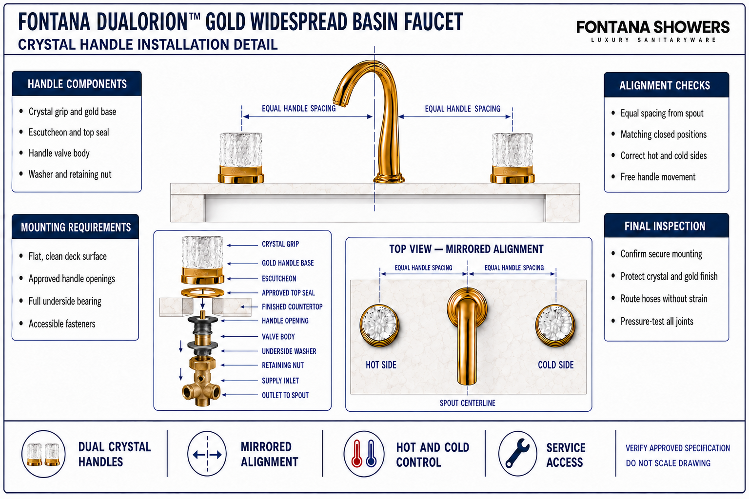
The enlarged section identifies the exposed crystal grip and gold escutcheon, finished deck, valve body, approved sealing components, underside washer and retaining nut. The lower plan shows the mirrored relationship between both handles and the spout without inventing an unpublished hole diameter, rotation angle, spacing limit or tightening value.
Conceptual handle-installation diagram. Confirm the approved component order, valve orientation, hole layout, operating direction and tightening requirements before installation.
| Installation item | Required coordination | What it controls | Field verification |
|---|---|---|---|
| Crystal grip and handle base | Present both handles uniformly in the closed position | Visual symmetry and intuitive operation | Pairwise alignment and movement check |
| Handle escutcheons | Seat both bases fully on clean, flat deck surfaces | Stable mounting and protection of finished openings | Full-contact inspection |
| Handle valve bodies | Pass squarely through the approved side openings | Correct orientation, engagement and handle travel | Orientation and thread inspection |
| Underside mounting hardware | Install washers and retaining nuts in approved order | Secure clamping without valve rotation or deck damage | Hand start and final stability check |
| Supply and outlet connections | Route to each valve without crossing, strain or interference | Correct hot/cold delivery and future service access | Functional, pressure and access test |
Crystal Handle Installation Process
Confirm the Three-Hole Layout
Verify both handle openings are positioned symmetrically around the approved spout centerline.
Identify Hot and Cold Sides
Confirm the required hot-side and cold-side locations before inserting either valve assembly.
Prepare Each Handle Assembly
Keep the crystal grip, gold base, escutcheon and approved sealing parts protected and correctly ordered.
Insert and Orient the Valves
Pass both valve bodies squarely through their openings and establish matching closed-position orientation.
Fit the Mounting Hardware
Install each underside washer and retaining nut in the approved order, starting the threads by hand.
Match and Tighten Both Handles
Hold both assemblies in mirrored alignment while tightening evenly from below.
Connect Supplies and Outlets
Route the hot, cold and valve-to-spout connections with relaxed bends and accessible joints.
Operate, Test and Reinspect
Check equal handle movement, correct water orientation, secure mounting and leak-free connections.
Crystal Handle Planning Considerations
Mirrored Spacing
Position both handles at equal distances from the spout centerline for a balanced three-hole layout.
Closed-Position Alignment
Set both crystal grips to present consistently when their valves are fully closed.
Full Escutcheon Contact
Use flat, clean mounting surfaces so both gold bases seat evenly without rocking or visible gaps.
Correct Valve Orientation
Orient each valve body for intuitive handle travel and unobstructed concealed connections.
Crystal and Finish Protection
Keep abrasive tools, impact and contaminated cloths away from the crystal grips and polished gold bases.
Below-Deck Access
Reserve clear space around both valves for fasteners, hoses, leak checks and future service tools.
Crystal Handle Installation Checklist
- Both handle openings are compatible with the approved layout and remain symmetrical around the spout.
- The finished deck is flat, clean and unobstructed beneath both handle escutcheons.
- Each approved sealing component is correctly positioned without folds or displacement.
- Both valve bodies pass squarely through their openings and are assigned to the correct hot or cold side.
- Underside washers bear fully and retaining nuts are installed in the approved sequence.
- The crystal grips match in the closed position and operate without contact or binding.
- Supply and outlet hoses maintain relaxed bends and remain clear of mounting hardware.
- Both assemblies have been pressure-tested, leak-checked and reinspected for rotation or movement.
Related Product and Planning Resources
Project verification: This page describes crystal-handle installation relationships but does not replace the approved product submittal or installation instructions. The countertop fabricator, plumbing engineer and licensed installer must verify the approved hole layout, deck compatibility, valve orientation, component order, tightening requirements, connection access and leak-free operation.









