


FontanaShowers® | Architectural and Installation Resource
Fontana DualOrion™ Gold Widespread Basin Faucet: Exploded Parts and Installation View
This comprehensive coordination resource organizes the complete three-hole faucet into its visible and concealed installation groups. It covers the high-arc spout, dual crystal handles, escutcheons, seals, mounting shanks, washers, retaining nuts, valve bodies, cartridges, hot-and-cold supplies, valve-to-spout connections, outlet assembly and final commissioning.

Three Fixture Groups Form One Coordinated Assembly
The center spout and two matching handle valves are installed through separate deck openings, then connected beneath the countertop. Organizing each component by location and sequence helps prevent omitted seals, reversed valves, crossed hoses, insufficient thread engagement, finish damage and inaccessible service joints.
- Above deck: Spout, crystal handles, bases, escutcheons and approved seals
- Through deck: Spout shank and two handle-valve bodies
- Below deck: Washers, retaining nuts, valves and connection fittings
- Water supplies: Separate accessible hot-and-cold isolation and inlet routes
- Controlled outlets: Both handle valves connected toward the center spout
- Spout outlet: Approved aerator components retained at the discharge end
- Commissioning: Alignment, operation, flushing and leak testing completed together
Complete Exploded Installation Relationship
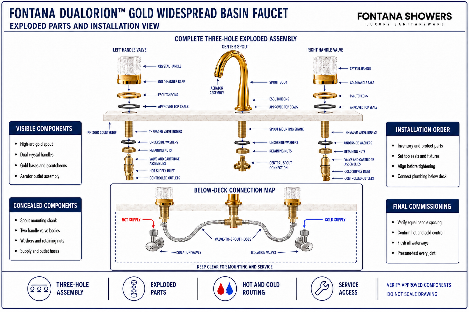
The enlarged view separates the product into left-handle, center-spout and right-handle groups, then continues through the countertop to the concealed mounting and plumbing connections. It establishes component order and system relationships without assigning unpublished hole sizes, thread standards, hose lengths, part numbers or tightening values.
Conceptual exploded-installation diagram. Confirm the supplied components, approved order, hole layout, connection arrangement and tightening requirements before assembly.
| Assembly group | Required coordination | What it establishes | Field verification |
|---|---|---|---|
| Center spout group | Install the spout, top seal, shank and underside hardware in order | Outlet alignment, stable mounting and spout access | Centerline and stability check |
| Left handle-valve group | Assign the hot side and preserve approved component sequence | Correct hot control and mirrored handle placement | Orientation and operation check |
| Right handle-valve group | Assign the cold side and match the opposite handle orientation | Correct cold control and balanced presentation | Orientation and operation check |
| Below-deck mounting hardware | Install seals, washers and retaining nuts on full bearing surfaces | Secure clamping and usable thread engagement | Component-order and stability check |
| Plumbing connection group | Route hot, cold and both valve outlets without strain or interference | Correct flow path, isolation and future service access | Functional and pressure test |
Complete Installation Sequence
Inventory and Organize Parts
Separate the center-spout group, hot-side group, cold-side group, mounting hardware and connections.
Confirm the Three-Hole Layout
Verify the approved openings, symmetrical handle locations, spout centerline and unobstructed underside zones.
Install the Center Spout
Place the top seal, insert the spout and loosely fit the underside washer and retaining nut.
Install Both Handle Valves
Position the hot and cold assemblies with matching closed orientation and loosely secure both from below.
Align and Tighten the Fixture
Center the outlet, equalize both handle gaps and tighten the three mounting stacks without rotation.
Connect Supplies and Outlets
Route hot and cold inlets to their valves, then connect both controlled outlets toward the spout.
Flush and Pressure-Test
Flush the building lines, restore water gradually and inspect every concealed connection under pressure.
Complete Final Commissioning
Verify alignment, hot/cold operation, handle movement, secure mounting, stream quality and service access.
Exploded-Assembly Planning Considerations
Complete Parts Inventory
Group each supplied component by spout, hot valve, cold valve, mounting or connection function.
Component Order
Keep seals, escutcheons, washers and retaining parts in the approved sequence for each assembly.
Mirrored Handle Geometry
Match handle spacing and closed-position orientation on both sides of the center spout.
Hot and Cold Assignment
Keep valve identities and supply routes clear before concealed plumbing connections are made.
Finish Protection
Protect every exposed gold and crystal surface throughout countertop and plumbing work.
Future Service Access
Reserve access to all fasteners, valve bodies, isolation valves, hoses and outlet components.
Exploded Parts and Installation Checklist
- All supplied visible, mounting, valve and connection components are present and grouped correctly.
- The countertop openings and underside clearances match current approved installation requirements.
- The spout is centered and both crystal handles have equal spacing and matching closed positions.
- Hot and cold valve assemblies are correctly assigned, oriented and securely mounted.
- All seals, washers and retaining nuts are installed in the approved order on full bearing surfaces.
- Supply and valve-to-spout hoses maintain relaxed bends and remain clear of basin hardware.
- Accessible isolation valves serve both supplies and all concealed joints remain inspectable.
- The completed faucet has been flushed, pressure-tested and verified for alignment and leak-free operation.
Related Product and Planning Resources
Project verification: This page describes complete assembly relationships but does not replace the approved product submittal or installation instructions. The countertop fabricator, plumbing engineer and licensed installer must verify supplied parts, hole layout, component order, valve orientation, tightening requirements, plumbing access, flushing and leak-free operation.









