


FontanaShowers® | Architectural and Installation Resource
Fontana DualOrion™ Gold Widespread Basin Faucet: Spout Mounting Assembly
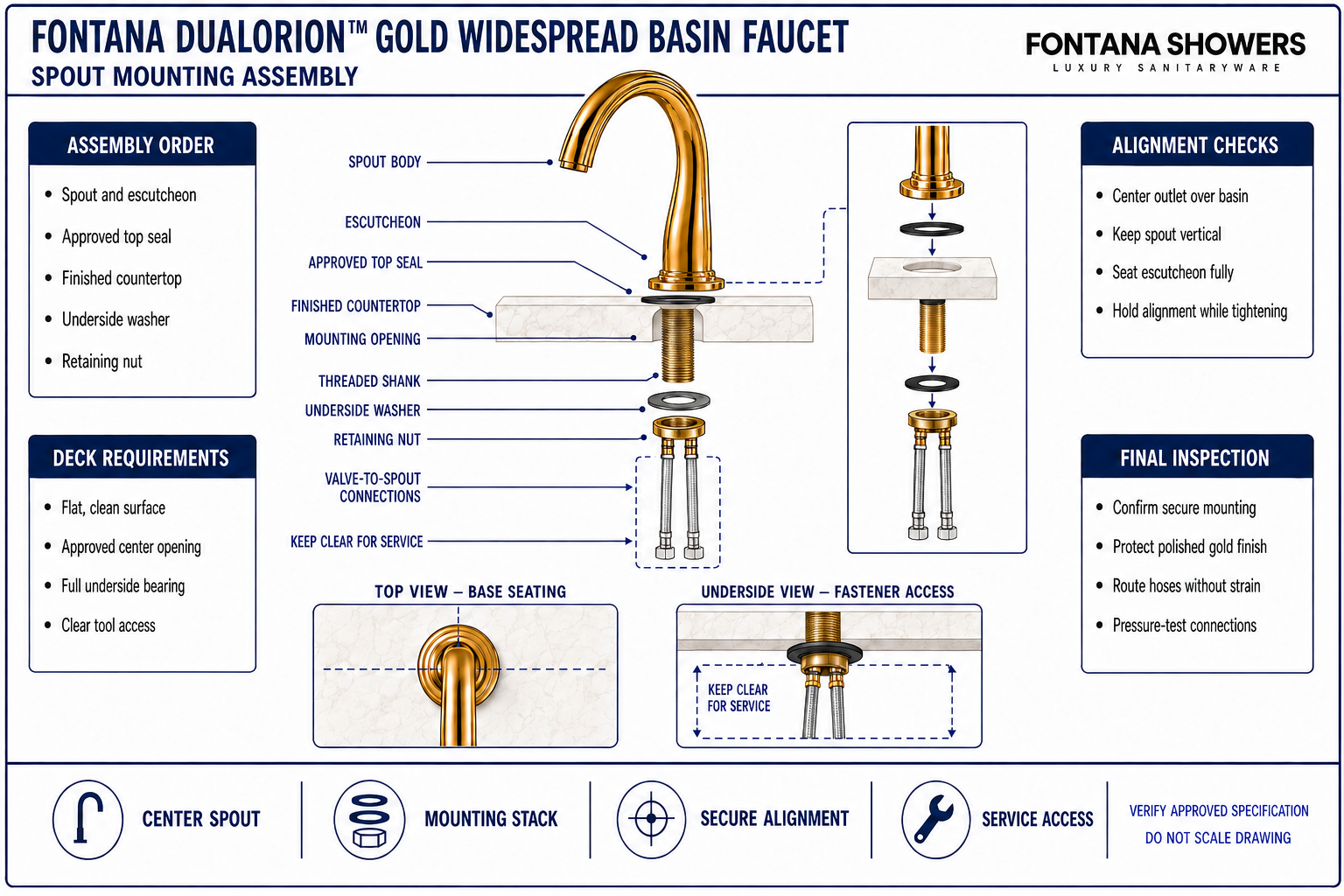
This installation-planning resource explains how the central high-arc spout is seated, aligned and secured to the finished countertop. It addresses the escutcheon and sealing surface, mounting opening, threaded shank, underside washer and retaining nut, valve-to-spout connections, final alignment, tightening sequence and access for inspection or future service.

The Spout Is Secured as a Complete Mounting Stack
The spout base must sit flat on a clean, stable deck while the concealed mounting parts clamp the assembly from below. Correct component order and even tightening preserve the gold finish, keep the spout vertical, maintain full bearing contact and leave the connection area accessible for hose installation, testing and maintenance.
- Finished-deck surface: Flat, clean and fully supporting the spout base
- Top seal: Approved gasket or sealing component beneath the escutcheon
- Mounting opening: Centered and compatible with the approved spout shank
- Threaded shank: Passed squarely through the deck without damaging threads
- Underside hardware: Washer and retaining nut installed in approved order
- Final alignment: Outlet centered over the basin before final tightening
- Connections: Relaxed valve-to-spout hoses with service access preserved
Spout Mounting Stack and Engagement
The enlarged section shows the relationship between the exposed spout base, finished deck, approved top seal, threaded shank, underside washer and retaining nut. The lower view identifies the protected connection and service zone without inventing an unpublished hole diameter, shank length, torque value or maximum deck thickness.
Conceptual mounting-stack diagram. Confirm the approved component order, mounting opening, deck compatibility and tightening requirements before installation.
| Assembly item | Installation requirement | What it protects | Field verification |
|---|---|---|---|
| Spout escutcheon | Seat fully on a clean, flat finished surface | Stable appearance and uniform base contact | Visual contact and alignment check |
| Top sealing component | Install in the approved position beneath the base | Protection of the mounting opening and finished deck | Component-order inspection |
| Threaded mounting shank | Pass squarely through the approved center opening | Full thread engagement without cross-threading | Opening compatibility and thread check |
| Washer and retaining nut | Seat evenly against the underside bearing surface | Secure clamping without spout rotation or deck damage | Hand start, alignment and final tightness check |
| Valve-to-spout connections | Route with smooth bends and preserve tool clearance | Leak-free operation and future service access | Pressure test and access demonstration |
Spout Mounting Process
Inspect the Mounting Area
Confirm that the center opening is correctly located and the finished deck is flat, clean and undamaged.
Protect the Gold Finish
Keep abrasive tools and unprotected metal surfaces away from the exposed spout and escutcheon.
Place the Approved Top Seal
Position the supplied gasket or approved sealing component in the specified order beneath the base.
Insert and Orient the Spout
Lower the threaded shank squarely through the opening and center the outlet over the basin.
Fit the Underside Hardware
Install the underside washer and retaining nut in the approved order, starting all threads by hand.
Align and Tighten Evenly
Hold the spout in final alignment while tightening from below without exceeding approved requirements.
Connect the Valve Outlets
Route both valve-to-spout connections with relaxed bends and keep them clear of fasteners and basin hardware.
Test and Reinspect
Operate both handles, pressure-test each connection and confirm the spout remains secure and correctly aligned.
Spout-Assembly Planning Considerations
Flat Bearing Surface
The escutcheon and underside hardware require stable, unobstructed surfaces for uniform clamping.
Approved Opening
Confirm the center-hole diameter from current approved documentation before drilling or fabrication.
Component Order
Keep the top seal, washer and retaining nut in the specified sequence so each part bears correctly.
Thread Engagement
Confirm adequate usable thread remains below the full counter assembly before final tightening.
Finish Protection
Use clean, nonabrasive protection while handling the polished gold spout and tightening concealed hardware.
Connection Access
Reserve clear space below the spout for fasteners, hose connections, leak checks and future tools.
Spout Mounting Assembly Checklist
- The center opening and full counter assembly are compatible with the approved mounting requirements.
- The finished deck is flat, clean and free of obstructions beneath the spout escutcheon.
- The approved top sealing component is correctly positioned without folds or displacement.
- The threaded shank passes squarely through the opening and all threads start freely by hand.
- The underside washer bears fully and the retaining nut is installed in the approved sequence.
- The spout outlet is centered over the basin and remains vertical during final tightening.
- Valve-to-spout connections have relaxed bends and remain clear of mounting hardware.
- The completed assembly has been pressure-tested, leak-checked and reinspected for movement.
Related Product and Planning Resources
Project verification: This page describes spout mounting relationships but does not replace the approved product submittal or installation instructions. The countertop fabricator, plumbing engineer and licensed installer must verify the approved opening, deck compatibility, component order, thread engagement, tightening requirements, connection access and leak-free operation.









