Fontana Touchless Faucets™ | Architectural and Engineering Resource
Fontana Lymora FS9099BGR Black Granite Automatic Motion Sensor Faucet:
Infrared Sensor Detection Zone Drawing
This infrared-sensor coordination resource is intended to support architects,
plumbing engineers, interior designers, contractors, countertop fabricators,
installers and facility managers coordinating the Fontana Lymora FS9099BGR
Black Granite automatic motion-sensor faucet. The drawing package communicates
the front-face infrared sensor location, hand-activation envelope, detection
axis, basin clearance, sensor coverage, reflection / interference zones,
stream alignment and typical touchless activation sequence.
Fontana Lymora FS9099BGR Infrared Touchless Waterfall Faucet
The FS9099BGR uses a front-facing infrared motion sensor to detect hand
presence and activate the waterfall stream without physical contact.
Proper coordination of the sensor field, basin geometry, faucet centerline
and reflective surroundings helps improve activation reliability and
reduce false triggering in commercial and hospitality lavatories.
- Model: FS9099BGR
- Sensor type: Infrared motion sensor
- Sensor location: Front face of faucet body
- Finish: Black Granite
- Installation: Single-hole deck mount
- Spout reach: 110 mm (4.33 in.)
- Spout height: 110 mm (4.33 in.)
- Overall faucet height: Approximately 175 mm (6.89 in.)
- Recommended basin clearance: Approximately 120 mm (4.72 in.) minimum
- Illustrated detection width: Approximately 110 mm (4.33 in.)
- Operation: Automatic touchless activation and shutoff
Required Infrared Sensor Detection Drawing Package
Each sensor-coordination drawing should use a consistent faucet centerline,
basin centerline and finished-countertop datum. The package should clearly
identify sensor position, activation envelope, detection axis, basin clearance,
stream landing zone, reflective-surface risks and the relationship between
the sensing field and the user’s natural hand-entry position.
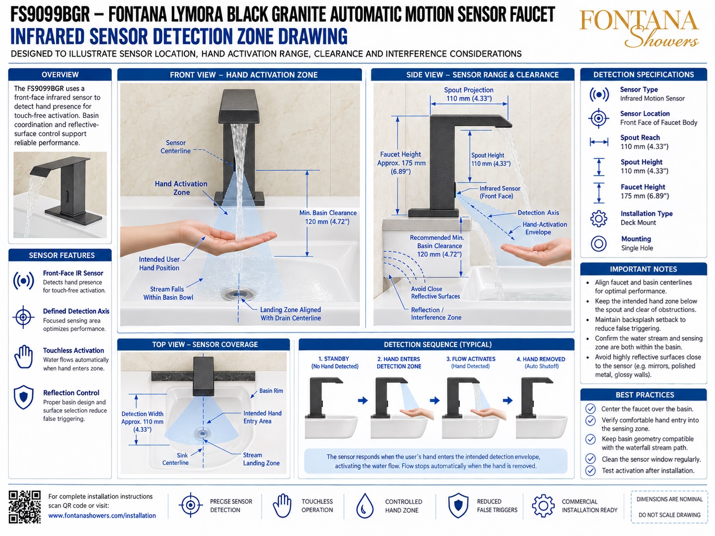
Infrared Sensor Detection Zone Drawing
Shows the complete touchless-sensor coordination for the Fontana Lymora FS9099BGR, including the sensor centerline, hand-activation envelope, side-view detection axis, top-view coverage, reflection / interference zone and automatic activation sequence.
Front View — Hand Activation Zone
Illustrates the infrared sensor centered on the faucet body and projecting a defined sensing field forward and downward toward the user’s hands. The intended activation area remains below the spout and within the basin footprint.
Sensor Centerline
Identifies the front-face infrared sensor aligned with the faucet centerline. Keeping the sensor centered with the basin supports predictable hand detection and helps keep the sensing envelope within the usable wash area.
Side View — Sensor Range & Clearance
Shows the 110 mm (4.33 in.) spout projection, 110 mm spout height, approximate 175 mm faucet height, detection axis and recommended minimum basin clearance of approximately 120 mm (4.72 in.).
Detection Axis & Hand Envelope
Defines the focused sensing direction projecting forward and downward from the faucet body. The intended hand position should enter this envelope naturally without requiring contact with the faucet.
Top View — Sensor Coverage
Shows the sensing field centered on the sink centerline and extending into the basin. The illustrated detection width is approximately 110 mm (4.33 in.) and overlaps the intended hand-entry and stream landing zones.
Reflection / Interference Control
Highlights the potential effect of mirrors, polished metal, glossy stone and reflective basin surfaces located close to the sensor. Adequate spacing and proper basin geometry help reduce false triggering.
Typical Detection Sequence
Illustrates the four-step operating sequence: standby, hand enters detection zone, flow activates and automatic shutoff after the hand is removed.
Final Sensor & Basin Verification
Before final handover, confirm faucet and basin centerlines, sensor clearance, hand-entry position, waterfall landing zone, basin geometry, reflective surfaces and reliable activation / shutoff under actual installed conditions.
Engineering note:
The sensor field and detection-zone graphics shown are nominal coordination
references. Actual infrared performance may vary with basin geometry,
material reflectivity, mounting position, ambient conditions, nearby objects
and installation tolerances. Final sensor range and activation behavior
should be verified on the installed Fontana Lymora FS9099BGR before project
handover.
Architectural, Sensor and Basin Coordination Considerations
Faucet / Basin Alignment
Center the faucet over the basin whenever practical so the sensing zone and water landing area remain comfortably within the usable bowl space.
Sensor Clearance
Keep the front-face sensor unobstructed by accessories, raised basin rims or nearby objects that could interfere with hand detection.
Reflective Surfaces
Avoid highly reflective finishes immediately in front of the sensor where reflected infrared energy could contribute to unintended activation.
Basin Geometry
Coordinate basin depth, rear-rim shape and bowl width with both the sensing field and waterfall stream so hand detection and water placement occur inside the basin.
Sensor Window Maintenance
Keep the sensor face clean and free of soap residue, mineral deposits and cleaning-product buildup that could reduce sensing consistency.
Post-Installation Testing
Test activation from several natural hand positions and confirm that flow starts and stops consistently without false triggers.
FontanaShowers Installation and Specification Resources
Professional Engineering and Accessibility References
Project verification:
Infrared sensor detection drawings are coordination tools and do not replace
approved project submittals. The architect, plumbing engineer, countertop
fabricator, contractor and licensed installer should verify sensor position,
basin geometry, hand-activation zone, reflective surfaces, stream landing,
faucet centerline, mounting conditions, accessibility criteria and locally
adopted plumbing requirements before final installation.
|
|
|