Fontana Touchless Faucet Systems™ |
Architectural and Engineering Resource
Fontana DSFD0024GS Vessel Sink and Chrome Touchless Sensor Faucet:
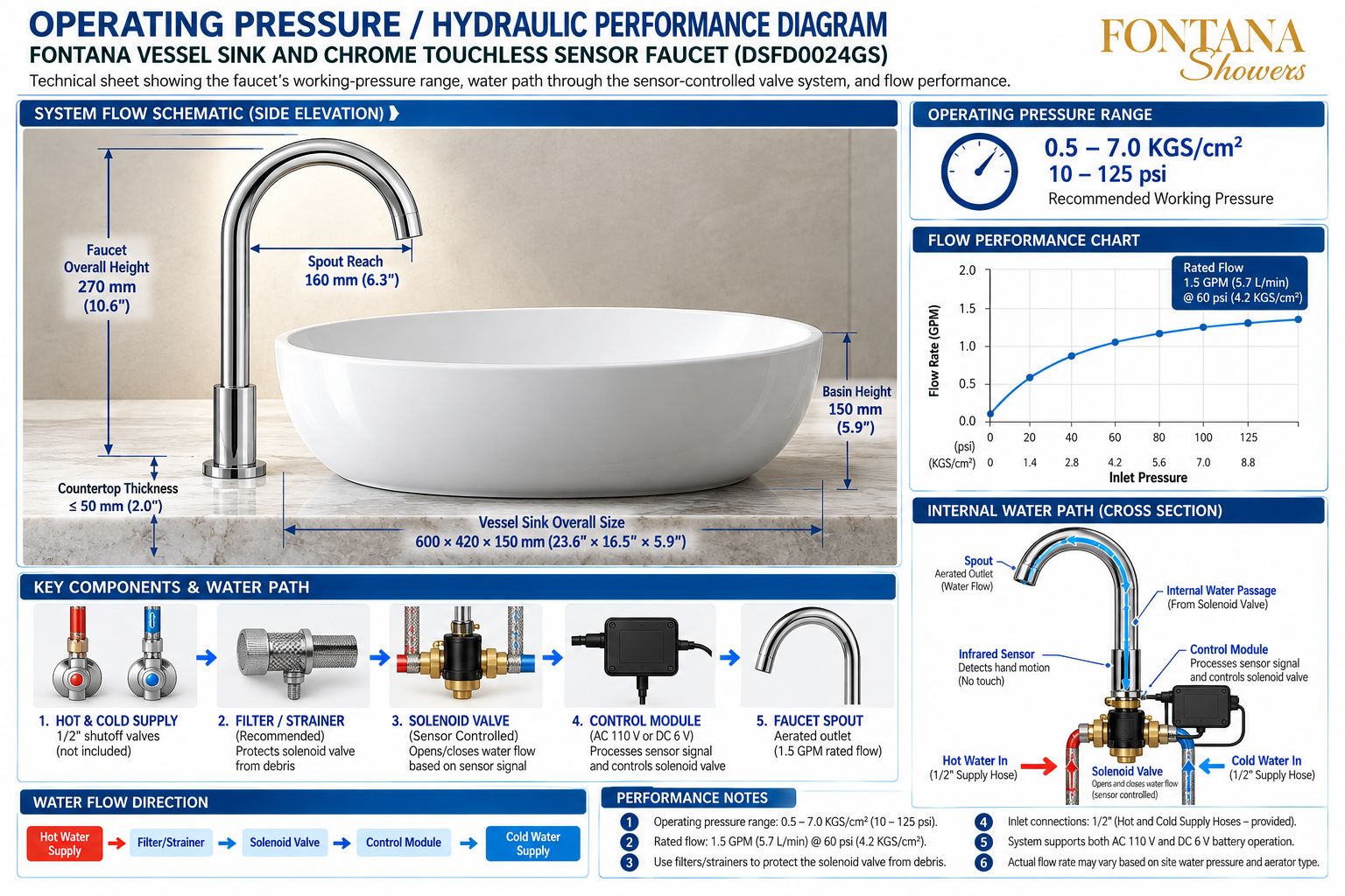
Operating Pressure / Hydraulic Performance Diagram
This hydraulic-performance resource is intended to support plumbing
engineers, contractors, installers, specifiers and maintenance personnel
coordinating the Fontana DSFD0024GS vessel sink and chrome touchless
sensor faucet combination. The technical drawing communicates the
faucet working-pressure range, rated flow reference, hot and cold inlet
connections, recommended filtration, sensor-controlled solenoid operation,
electronic control module and internal water path through the faucet
to the aerated outlet.
Fontana DSFD0024GS Hydraulic Performance & Water-Flow System
The DSFD0024GS touchless faucet receives hot and cold water
through separate supply connections. The illustrated system
includes shutoff points, recommended filter / strainer protection,
a sensor-controlled solenoid valve, an electronic control module
and an internal faucet passage leading to the aerated outlet.
The drawing also provides operating-pressure and flow-performance
references for system coordination.
-
Model:
DSFD0024GS
-
Faucet overall height:
270 mm (10.6 in.)
-
Spout reach:
160 mm (6.3 in.)
-
Vessel sink overall size:
600 × 420 × 150 mm
(23.6 × 16.5 × 5.9 in.)
-
Basin height:
150 mm (5.9 in.)
-
Countertop thickness shown:
≤ 50 mm (2.0 in.)
-
Operating pressure range:
0.5–7.0 KGS/cm²
-
Pressure reference:
10–125 psi
-
Rated flow:
1.5 GPM (5.7 L/min.)
-
Rated-flow reference:
60 psi (4.2 KGS/cm²)
-
Inlet connections:
1/2-inch hot and cold supply hoses
-
Power support:
AC 110 V or DC 6 V battery operation
-
Outlet:
Aerated faucet outlet
Required Hydraulic Performance Drawing Package
Each hydraulic coordination drawing should identify the faucet and
vessel-sink dimensions, operating-pressure range, rated-flow reference,
hot and cold supply connections, recommended filter / strainer,
sensor-controlled solenoid valve, control module, internal water
passage and aerated outlet. Installed performance should be verified
under actual project water-pressure conditions.
Operating Pressure / Hydraulic Performance Diagram
Provides the complete relationship between faucet dimensions,
working pressure, flow performance, supply connections,
solenoid control and internal water delivery.
System Flow Schematic — Side Elevation
Shows the chrome faucet and vessel sink together with the
principal dimensional references used for installation and
hydraulic coordination.
Faucet & Vessel Dimensions
Identifies the 270 mm faucet height, 160 mm spout reach,
150 mm basin height, 600 × 420 × 150 mm vessel size and
countertop thickness up to 50 mm.
Operating Pressure Range
Shows a recommended working-pressure range of
0.5–7.0 KGS/cm², corresponding to approximately
10–125 psi.
Flow Performance Chart
Illustrates increasing outlet flow with rising inlet pressure
and identifies a rated reference of 1.5 GPM
(5.7 L/min.) at 60 psi (4.2 KGS/cm²).
Hot & Cold Supply
Shows separate 1/2-inch hot and cold water supply connections
feeding the touchless faucet control system.
Filter / Strainer
Identifies recommended upstream filtration intended to
protect the solenoid valve from debris entering through
the water supply.
Solenoid Valve & Control Module
Shows the sensor-controlled solenoid opening and closing
the water path while the electronic control module processes
the sensor signal.
Internal Water Path
Illustrates the controlled water path from the solenoid valve,
up through the faucet body and curved spout, to the aerated
outlet.
Engineering note:
The pressure range, flow values, dimensions and component
relationships shown are technical coordination references for the
illustrated DSFD0024GS configuration. Actual hydraulic performance
may vary according to site water pressure, supply piping,
filter / strainer condition, aerator configuration and installed
system conditions.
Key Components & Water Path
1. Hot & Cold Supply
Separate hot and cold supplies provide water to the system
through the illustrated 1/2-inch inlet connections.
Shutoff valves are shown as part of the installation layout.
2. Filter / Strainer
A recommended filter or strainer helps protect the
sensor-controlled valve from debris before water enters
the solenoid assembly.
3. Solenoid Valve
The sensor-controlled solenoid opens and closes the water
path according to commands received from the electronic
control system.
4. Control Module
The control module processes the infrared sensor signal and
controls solenoid-valve operation using the supported
AC 110 V or DC 6 V power arrangement.
5. Faucet Spout
Water moves through the internal faucet passage and exits
at the aerated spout outlet, which is identified with a
1.5 GPM rated-flow reference.
Infrared Sensor
The sensor detects hand motion without touch and provides
the activation signal used by the controller to operate the
solenoid valve.
Hydraulic Performance & Supply Coordination
Working Pressure
Coordinate the installation with the illustrated
0.5–7.0 KGS/cm² (10–125 psi) operating-pressure range.
Rated Flow Reference
The technical drawing identifies a rated flow of
1.5 GPM (5.7 L/min.) at 60 psi (4.2 KGS/cm²).
Supply Hose Condition
Keep hot and cold inlet hoses properly connected and clear
of restrictions that could affect available water flow.
Filter Condition
Inspect the recommended filter / strainer periodically so
debris accumulation does not interfere with solenoid-valve
operation.
Solenoid Response
Confirm the valve opens and closes correctly when the
electronic controller receives the faucet sensor signal.
Outlet Condition
Inspect the aerated faucet outlet if actual flow differs
from the expected performance shown in the technical chart.
Internal Water Path & Touchless Control Sequence
Water Inlets
Hot and cold water enter through the separate supply hoses
connected to the valve assembly below the faucet.
Sensor Detection
The infrared sensor detects hand motion and sends an
activation signal to the electronic controller.
Controller Response
The control module processes the sensor signal and provides
the command required to operate the solenoid valve.
Solenoid Activation
The solenoid opens the controlled water path, allowing
water to enter the faucet's internal passage.
Internal Passage
Controlled water travels upward through the faucet body
and follows the internal passage through the curved spout.
Aerated Discharge
Water exits the faucet through the aerated outlet and is
delivered into the vessel sink.
Hydraulic Performance & Commissioning Checks
Pressure Check
Verify site water pressure and confirm the faucet operates
within the working-pressure range shown in the technical
drawing.
Flow Check
Confirm stable outlet flow and compare actual performance
with the 1.5 GPM at 60 psi rated-flow reference.
Supply Check
Verify hot and cold inlet hoses are correctly installed,
fully open and free from restrictions or leakage.
Filter Inspection
Check filters or strainers for construction debris before
diagnosing low flow as a valve or faucet problem.
Touchless Activation
Activate the faucet through the infrared sensor and confirm
the controller and solenoid produce reliable water delivery.
Leak Inspection
Inspect all inlet hoses, solenoid connections and faucet
connections while the system is pressurized and operating.
Performance Notes
Operating Pressure Range
0.5–7.0 KGS/cm²
(10–125 psi).
Rated Flow
1.5 GPM (5.7 L/min.) at
60 psi (4.2 KGS/cm²).
Filter / Strainer
Recommended to help protect the solenoid valve from
debris in the incoming water supply.
Inlet Connections
1/2-inch hot and cold supply hoses are shown for the
illustrated system.
Power Support
The illustrated system supports AC 110 V and DC 6 V
battery operation.
Actual Flow
Actual flow may vary according to site water pressure
and aerator type.
FontanaShowers Installation and Specification Resources
Professional Plumbing and Engineering References
Project verification:
Hydraulic performance drawings are technical coordination tools and
do not replace approved project submittals or manufacturer instructions.
The architect, plumbing engineer, contractor and licensed installer
should verify available water pressure, hot and cold inlet connections,
supply-hose condition, filter / strainer arrangement, solenoid operation,
controller configuration, aerator type, outlet flow and locally adopted
plumbing requirements before final installation and commissioning.
|
|
|