Fontana Touchless Faucets™ | Architectural and Engineering Resource
Fontana Lymora FS9099BGR Black Granite Automatic Motion Sensor Faucet:
Sensor Control System Diagram
This sensor-control resource is intended to support architects, plumbing
engineers, electrical coordinators, contractors, installers and facility
managers coordinating the Fontana Lymora FS9099BGR Black Granite automatic
motion-sensor faucet. The drawing package communicates the front-face infrared
sensor, electronic controller, automatic solenoid valve, water-flow command,
hand-entry coverage, timed shutoff logic and under-deck service-access
requirements.
Fontana Lymora FS9099BGR Infrared Sensor Control System
The FS9099BGR uses a front-facing infrared sensor to detect hand
presence, send a signal to an electronic controller and command an
under-deck solenoid valve to open or close the water path automatically.
This control sequence supports hygienic, touch-free operation and
automatic shutoff when the user leaves the sensing zone.
- Model: FS9099BGR
- Sensor type: Infrared motion sensor
- Sensor location: Front face of faucet body
- Controller: Electronic control module
- Valve type: Automatic solenoid valve
- Installation: Single-hole deck mount
- Spout reach: 110 mm (4.33 in.)
- Overall faucet height: Approximately 175 mm (6.89 in.)
- Water supply: Hot and cold
- Operation: Automatic hands-free activation
- Shutoff: Controller-commanded automatic closure
Required Sensor Control System Drawing Package
Each control-system drawing should use a consistent component-identification
scheme, signal-flow convention and service-access notation. The package
should clearly identify the infrared sensor, hand-entry zone, controller,
solenoid valve, signal path, automatic shutoff sequence, supply connections
and accessible under-deck service components.
Sensor Control System Diagram
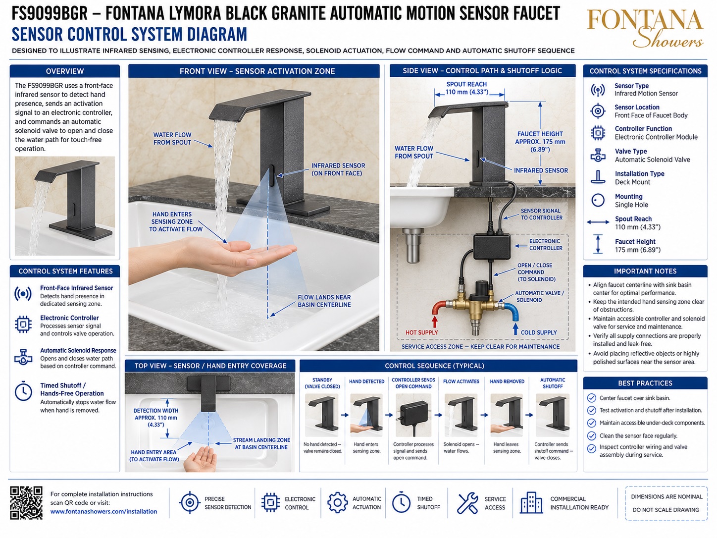
Shows the complete touchless-control architecture for the Fontana Lymora FS9099BGR, including the front-face infrared sensor, electronic controller, automatic solenoid valve, water-supply path, service zone and typical automatic shutoff sequence.
Front View — Sensor Activation Zone
Illustrates the infrared sensor integrated into the faucet body and aimed toward the user’s natural hand position below the spout. When a hand enters the sensing field, the controller initiates water flow through the faucet.
Infrared Sensor
Identifies the front-face motion sensor as the initial detection component. It monitors the hand-entry zone and sends an activation signal to the electronic controller when user presence is detected.
Electronic Controller
Acts as the logic interface between the infrared sensor and the solenoid valve. The controller processes the sensor signal and sends open or close commands to regulate water flow.
Automatic Solenoid Valve
Controls the water path below the countertop. The solenoid opens when commanded by the controller and closes when the user leaves the sensing zone or the shutoff logic is triggered.
Side View — Control Path & Shutoff Logic
Shows the faucet, sensor, controller, solenoid valve, hot and cold supplies and under-deck service area in one coordinated section, highlighting the signal path from sensor detection to water-flow control.
Top View — Sensor / Hand Entry Coverage
Shows the hand-entry zone centered with the faucet and basin. The illustrated detection width is approximately 110 mm (4.33 in.), aligned with the intended stream landing area.
Typical Control Sequence
Illustrates the sequence from standby, to hand detection, controller open command, flow activation, hand removal and automatic shutoff. The sequence supports fully hands-free faucet operation.
Service Access & Functional Verification
Coordinates access to the controller, solenoid, wiring, hoses and shutoff valves. Before handover, verify reliable activation, automatic shutoff, leak-free connections and unobstructed sensor performance.
Engineering note:
The sensing field, controller logic and shutoff sequence shown are nominal
coordination references. Final detection range, controller settings,
solenoid timing, electrical requirements, wiring arrangement and service
clearances should be verified against the approved Fontana Lymora FS9099BGR
installation documentation and tested under actual installed conditions.
Sensor, Plumbing and Service Coordination Considerations
Faucet / Basin Alignment
Center the faucet over the basin so the sensing zone and water landing area remain comfortably within the usable bowl space.
Sensor Clearance
Keep the front-face sensor unobstructed by accessories, raised rims or nearby reflective objects that could interfere with detection.
Controller Accessibility
Install the electronic controller in an accessible under-deck location where wiring and service connections can be inspected or replaced.
Solenoid Service Zone
Maintain clear access around the automatic valve so the solenoid can be isolated, tested, removed or replaced without disturbing permanent finishes.
Wiring Protection
Route sensor and controller wiring away from sharp edges, pinch points and moisture exposure while maintaining enough slack for service.
Post-Installation Testing
Test hand detection, controller response, solenoid opening and automatic shutoff under actual installed conditions before final commissioning.
FontanaShowers Installation and Specification Resources
Professional Engineering and Accessibility References
Project verification:
Sensor-control-system drawings are coordination tools and do not replace approved
project submittals. The architect, plumbing engineer, electrical coordinator,
contractor and licensed installer should verify sensor location, controller
configuration, solenoid operation, wiring, shutoff logic, supply connections,
service access, basin alignment, accessibility criteria and locally adopted
plumbing and electrical requirements before commissioning.
|
|
|