Fontana Touchless Fixtures™ | Architectural and Engineering Resource
Fontana Countertop Faucet & Soap Dispenser:
Soap Dispensing System Diagram
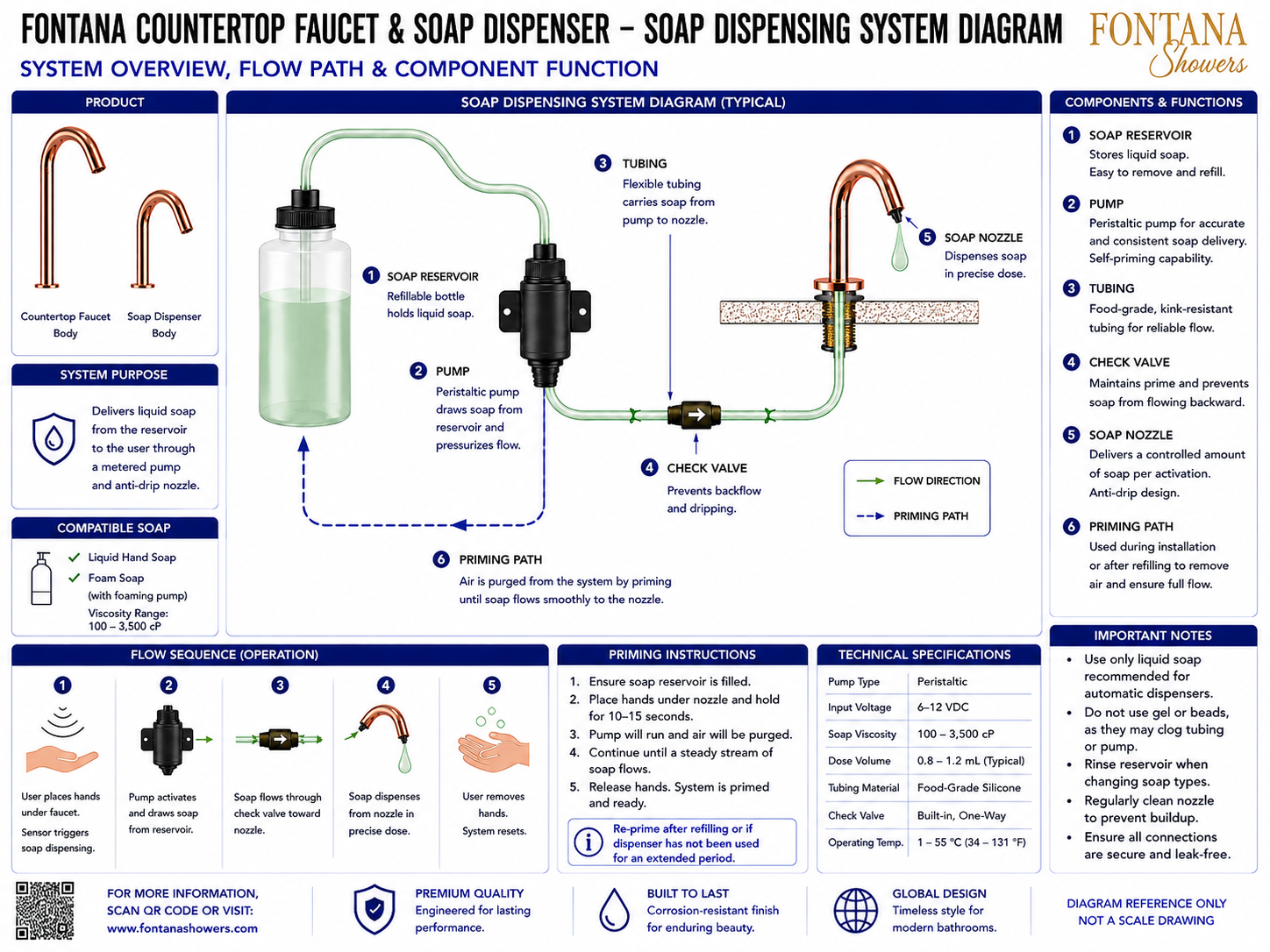
This soap-dispensing-system resource is intended to support architects,
plumbing engineers, contractors, installers, maintenance personnel and
facility managers coordinating the Fontana countertop automatic soap
dispenser within commercial and residential lavatory environments. The
drawing identifies the refillable reservoir, peristaltic pump, flexible
tubing, one-way check valve, soap nozzle, flow direction, priming path,
operating sequence and typical system specifications.
Fontana Automatic Soap Dispensing System
This coordinated under-counter system stores liquid soap in a refillable
reservoir and uses a peristaltic pump to move soap through food-grade
flexible tubing toward the dispenser nozzle. A built-in one-way check
valve helps maintain prime, reduce backflow and support consistent
metered dispensing at each activation.
- System purpose: Automatic liquid-soap delivery
- Soap reservoir: Refillable bottle
- Pump type: Peristaltic metering pump
- Tubing material: Food-grade silicone
- Check valve: Built-in one-way valve
- Nozzle type: Controlled anti-drip soap outlet
- Flow direction: Reservoir → Pump → Check Valve → Nozzle
- Input voltage: 6–12 VDC
- Soap viscosity range: 100–3,500 cP
- Typical dose volume: 0.8–1.2 mL
- Operating temperature: 1–55 °C (34–131 °F)
- Compatible soap: Liquid hand soap; foam soap with appropriate pump
Required Soap Dispensing System Drawing Package
Each drawing should use a consistent component numbering system, flow
direction graphic and priming-path notation. The package should clearly
identify the reservoir, pump, tubing, check valve, nozzle, connection
points and operating sequence. Soap compatibility, priming requirements,
dose range and maintenance access should be documented for installation,
commissioning and service.
Soap System Overview
Shows the complete relationship between the soap reservoir, peristaltic pump, flexible tubing, check valve and dispenser nozzle. This drawing provides an overall reference for installation, priming, service planning and project submittals.
Soap Reservoir
Identifies the refillable bottle that stores liquid soap beneath the countertop. The reservoir should remain upright, securely supported and accessible for removal, cleaning and refilling.
Peristaltic Pump
Illustrates the pump that draws soap from the reservoir and pressurizes the delivery line. The pump supports accurate metering, self-priming and repeatable soap delivery.
Flexible Tubing
Shows the food-grade, kink-resistant tubing connecting the reservoir, pump, check valve and nozzle. Tubing should be routed without pinching, excessive bends or contact with sharp edges.
One-Way Check Valve
Identifies the valve that maintains system prime and reduces reverse flow after dispensing. Correct orientation is essential for reliable operation and reduced dripping at the nozzle.
Soap Nozzle
Shows the final dispensing outlet at the countertop fixture. The nozzle delivers a controlled quantity of soap and incorporates an anti-drip configuration for cleaner operation.
Flow Direction
Defines the normal soap path from the reservoir through the pump and check valve to the nozzle. Flow-direction arrows should remain visible in installation and service documentation.
Priming Path
Illustrates the route used to purge air during initial installation or after refilling. Priming should continue until a steady, uninterrupted stream reaches the dispenser nozzle.
Operating Sequence
Summarizes user activation, pump operation, soap movement through the check valve, metered dispensing and system reset. This sequence supports commissioning and troubleshooting.
Engineering note:
The soap-system diagram is a coordination reference and should not be scaled.
Use only compatible liquid soap and approved components. Verify tubing
routing, valve orientation, pump operation, priming, dose volume and
maintenance procedures against the current product specification and
installation instructions before placing the system into service.
Installation and Maintenance Coordination Considerations
Soap Compatibility
Use liquid soap within the specified viscosity range and avoid gels, beads or suspended particles that may restrict the tubing or pump.
Tubing Routing
Route tubing in smooth curves without kinks, flattening, excessive length or contact with sharp cabinet edges.
Priming
Prime the system after installation, after refilling or whenever the dispenser has been unused long enough for air to enter the line.
Check-Valve Orientation
Confirm the one-way valve is installed in the indicated flow direction so soap can reach the nozzle and backflow is minimized.
Nozzle Cleaning
Inspect and clean the nozzle regularly to prevent dried soap buildup, reduced flow and irregular dose delivery.
Service Access
Keep the reservoir, pump, tubing connections and check valve accessible for inspection, cleaning, refilling and component replacement.
FontanaShowers Installation and Specification Resources
FontanaShowers Product CatalogProduct information, finish options and technical documentation for Fontana touchless bathroom and commercial fixtures.
FontanaShowers Installation HubCentral installation resource for automatic soap dispensers, pumps, reservoirs, tubing and touchless faucets.
Automatic Sensor Faucet CollectionExplore touchless faucet systems, coordinated soap dispensers and commercial handwashing solutions.
Faucet BIM and Design ResourcesArchitectural and coordination resources supporting fixture selection, documentation and multidisciplinary model development.
Soap Dispenser ResourcesProduct and installation information for refillable reservoirs, pumps, tubing, check valves and dispensing nozzles.
Fixture Installation ResourcesGeneral installation information covering priming, tubing, testing, cleaning and maintenance.
Professional Engineering and Accessibility References
Project verification:
Soap dispensing system diagrams are coordination and service tools and do not
replace approved project submittals. The plumbing engineer, contractor,
facility manager and qualified installer should verify soap compatibility,
pump type, tubing material, check-valve orientation, nozzle condition,
priming procedure, dose settings, service access and manufacturer requirements
before installation, commissioning or maintenance.
|
|
|