Touchless Faucet & Soap Dispenser BIM/MEP Coordination | Fontana
Fontana BIM / MEP Coordination™
Touchless System
BIM / MEP Coordination
Coordinate automatic faucets and soap dispensers across architectural models, plumbing services, electrical systems, millwork and facility-access requirements before construction.
ModelGeometry and placement
ConnectPlumbing and electrical
CoordinateClearances and access
VerifyApproved product data
Coordination Purpose
Model the interfaces—not just the visible fixtures
A faucet and dispenser family may show useful visible geometry, but coordinated construction also requires mounting zones, water and soap routing, power, controllers, access and clearance from waste and millwork.
Use BIM content as a coordination aid. Approved product data and model-specific installation documents remain the controlling source for dimensions, connections and installation requirements.
Coordination Model
Information the BIM environment should communicate
Product IdentityManufacturer, product code, fixture type, mounting method and approved document references.
Visible GeometryFaucet, dispenser, base, outlet projection and relationship to basin and counter.
Mounting ReferencesHost surface, openings, centerlines, finished references and support conditions.
Service ConnectionsWater, soap, power and control connection points associated with the selected system.
Equipment ZonesControllers, valves, filters, power components, reservoirs and maintainable routing.
Clearance ObjectsService access, accessibility, sensor coverage and other non-physical coordination zones.
Model Exchange
Assign each interface to the right discipline
The coordination model should make ownership and verification visible before fabrication and rough-in.
ArchitecturalFixture locations, elevations, counter construction and basin coordination.
PlumbingSupply, shutoff, filtration, mixing, waste, valve and soap delivery.
ElectricalPower source, protected routing, connection and accessible control equipment.
MillworkAccess panels, internal obstructions, equipment supports and service reach.
Clash Review
Common coordination conflicts to resolve
|
Interface
|
Potential conflict
|
Model check
|
|
Faucet / Basin
|
Poor stream landing or insufficient user space
|
Confirm spout, basin and intended hand position together
|
|
Controls / Waste
|
Trap or drain routing occupies equipment space
|
Coordinate actual drain geometry with service components
|
|
Reservoir / Millwork
|
Drawer, brace or fixed panel blocks filling and replacement
|
Show reservoir and service path inside the cabinet model
|
|
Equipment / Access
|
Concealed component falls behind inaccessible construction
|
Model access panel and maintenance approach
|
|
Equipment / ADA
|
Controls or enclosures intrude into required clearances
|
Use clearance objects for the complete accessible condition
|
Coordination Workflow
Advance the model with verified information
Do not allow placeholder geometry to become unverified construction information.
01SelectConfirm exact faucet, dispenser and system components.
02PlaceCoordinate fixtures with basin, counter and user position.
03ConnectAdd verified plumbing, soap, power and control interfaces.
04ReviewResolve clashes, clearances, access and document references.
Supporting Resources
Connect the model to the installation package
BIM content does not replace approved product documentsConfirm model version, product code and project status before using geometry or parameters for construction. Installation dimensions, connections and service requirements must be verified against the approved submittal and model-specific instructions.
BIM / MEP Questions
Model and document coordination
What should be verified before placing a BIM family?
Confirm the exact product code, mounting type, model revision and available product documentation. Do not substitute a visually similar family without technical verification.
Should concealed components be represented?
Yes, when needed for coordination. Represent equipment zones, connection points and service access so plumbing, electrical, millwork and waste systems can be reviewed together.
Can BIM geometry be used directly for fabrication?
Only after its status and accuracy are confirmed against approved product information. A coordination family should not automatically be treated as a fabrication model.
Which clashes deserve early review?
Review conflicts among fixtures, basins, traps, water routing, controllers, power, soap reservoirs, millwork supports, access panels and required accessibility clearances.
Touchless Installation Library
Return to the touchless installation structure
Use the engineering sheet for the complete installation package or return to the touchless hub for every supporting guide.
|
|
Fontana BIM / MEP Coordination™ | Architectural and Engineering Resource
Fontana Combination Faucet & Soap Dispenser:
BIM / MEP Coordination Drawing
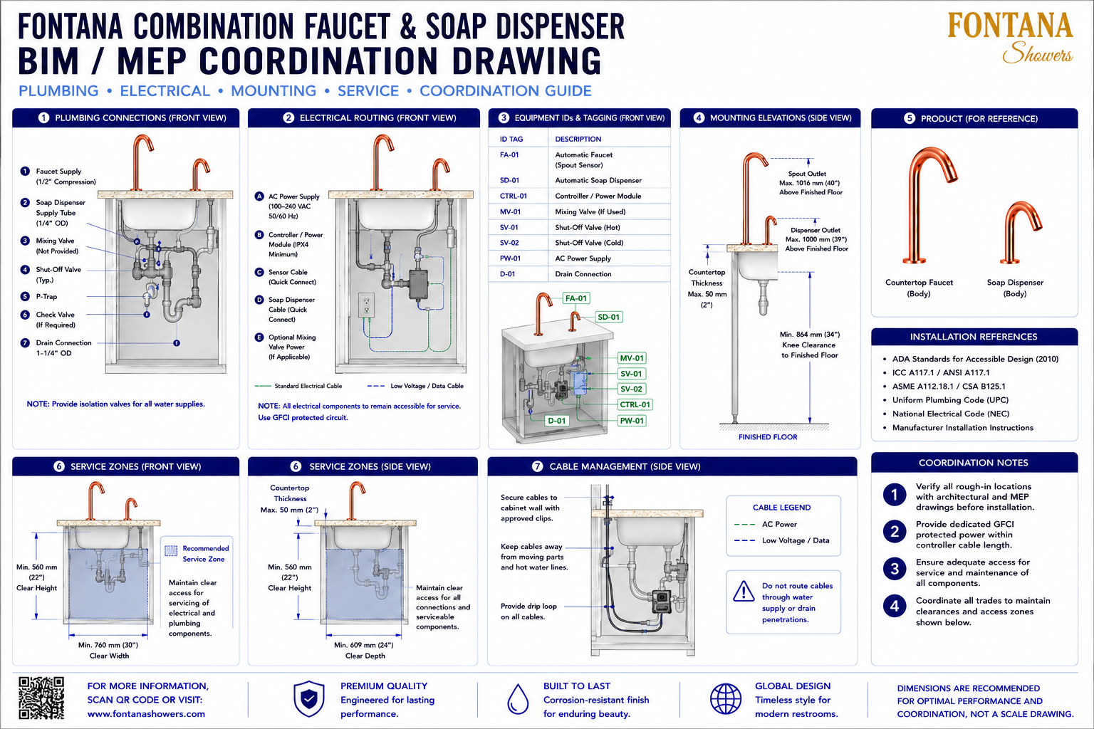
This BIM / MEP coordination resource is intended to support architects,
plumbing engineers, electrical engineers, BIM coordinators, contractors and
installers integrating the Fontana automatic countertop faucet and touchless
soap dispenser into coordinated construction documents. The drawing identifies
plumbing connections, electrical routing, equipment tags, mounting elevations,
service zones, cable management requirements and coordination notes needed to
reduce conflicts between architectural, plumbing, electrical and cabinetry systems.
Fontana Automatic Faucet and Soap Dispenser BIM / MEP Coordination System
This coordinated fixture arrangement combines automatic water delivery
and touchless soap dispensing with concealed plumbing, power and control
components. The drawing supports multidisciplinary model development,
rough-in verification, equipment tagging, accessible installation and
long-term service planning beneath the countertop.
- Fixture configuration: Countertop automatic faucet and touchless soap dispenser
- Coordination scope: Plumbing, electrical, mounting, service and accessibility
- Faucet supply: 1/2-inch compression
- Soap-dispenser supply tube: 1/4-inch OD
- Drain connection: 1-1/4-inch OD
- AC power: 100–240 VAC, 50/60 Hz
- Controller / power module: IPX4 minimum
- Maximum countertop thickness: 50 mm (2 in.)
- Maximum faucet outlet height: 1016 mm (40 in.) AFF
- Maximum dispenser outlet height: 1000 mm (39 in.) AFF
- Minimum knee clearance: 864 mm (34 in.)
- Recommended service zone: 760 × 609 × 560 mm (30 × 24 × 22 in.)
Required BIM / MEP Coordination Drawing Package
Each drawing should use a consistent equipment-tagging convention,
centerline reference and service-zone notation. The package should clearly
identify plumbing connections, AC and low-voltage routing, controller
locations, mounting heights, accessibility clearances, cabinet service
envelopes and cable-management requirements. All trade interfaces should be
verified before rough-in and fabrication.
Plumbing Connection Coordination
Shows faucet supply, soap-dispenser tubing, mixing valve, shut-off valves, P-trap, check valve and drain connection. Provide accessible isolation valves and coordinate all rough-in locations with the plumbing plan.
Electrical Routing & Power
Illustrates AC power, controller/power module, quick-connect sensor wiring, soap-dispenser cable and optional mixing-valve power. Use GFCI protection where required and keep all electrical components accessible for service.
Equipment IDs & BIM Tagging
Uses coordinated equipment IDs such as FA-01, SD-01, CTRL-01, MV-01, SV-01, SV-02, PW-01 and D-01 to simplify architectural, plumbing, electrical and BIM documentation.
Mounting Elevations
Shows faucet and soap-dispenser outlet elevations above finished floor, countertop thickness and required knee clearance. Final elevations should be coordinated with accessibility criteria and basin geometry.
Service Zones & Access Clearances
Defines a recommended under-counter service envelope of approximately 760 mm wide, 609 mm deep and 560 mm high for plumbing, electrical and control components.
Cable Management
Shows AC and low-voltage/data cables secured to cabinet surfaces, kept clear of moving parts and hot-water lines, and provided with drip loops. Do not route cables through water-supply or drain penetrations.
Accessibility Coordination
Coordinates outlet heights, knee clearance and user approach with the applicable ADA, ICC/ANSI and project-specific accessibility requirements.
Trade Coordination
Align plumbing, electrical, cabinetry, countertop and architectural work so rough-ins, penetrations, service clearances and component mounting do not conflict during construction.
Final Rough-In Verification
Confirms all equipment tags, power locations, supply connections, drain positions, mounting elevations and service zones before installation and commissioning.
Engineering note:
The BIM / MEP coordination drawing is a reference document and should not be
scaled. Verify all rough-in locations, equipment IDs, mounting elevations,
power requirements, plumbing connections, service zones and accessibility
dimensions against approved architectural and MEP drawings, project
submittals and manufacturer installation instructions before construction.
BIM, MEP and Installation Coordination Considerations
Plumbing Rough-In
Coordinate water supplies, drain location, valves and optional mixing components before cabinet and countertop fabrication.
Electrical Power
Provide appropriately protected AC power and maintain access to the controller, power supply and low-voltage quick-connect cables.
Equipment Tagging
Use consistent tags across architectural, plumbing, electrical and BIM models so every component can be traced between disciplines.
Service Access
Maintain clear front and side access for all serviceable plumbing and electrical components beneath the countertop.
Cable Separation
Keep AC and low-voltage/data cables organized, protected from moisture and separated from hot-water lines and moving hardware.
Accessibility Review
Verify final fixture elevations, knee space and reach conditions against the project accessibility requirements before installation.
FontanaShowers Installation and Specification Resources
FontanaShowers Product Catalog
Product information, finish options and technical documentation for Fontana automatic faucets and soap dispensers.
FontanaShowers Installation Hub
Central installation resource for automatic faucets, soap dispensers and associated plumbing and electrical components.
Automatic Sensor Faucet Collection
Explore commercial touchless faucet configurations, control systems, power options and finishes.
BIM and Design Resources
Architectural and engineering resources supporting fixture coordination, model development and construction documentation.
Touchless Soap Dispenser Resources
Product and installation information for automatic dispensers, pumps, reservoirs, tubing and control systems.
Fixture Installation Resources
General installation information covering rough-in, mounting, plumbing, electrical connections, testing and maintenance.
Professional Engineering and Accessibility References
Project verification:
BIM / MEP coordination drawings are multidisciplinary coordination tools and do
not replace approved construction documents or project submittals. The architect,
plumbing engineer, electrical engineer, BIM coordinator, contractor and qualified
installer should verify equipment tags, rough-in locations, power requirements,
plumbing connections, mounting elevations, service clearances, accessibility
criteria and locally adopted codes before fabrication, installation and commissioning.
|
|
|