Fontana Touchless Faucets™ | Architectural and Engineering Resource
Fontana Brio PrimeSense™ Line FS-1095GMG Gun Metal Gray Touchless Bathroom Faucet:
Single-Hole Deck Mount Detail
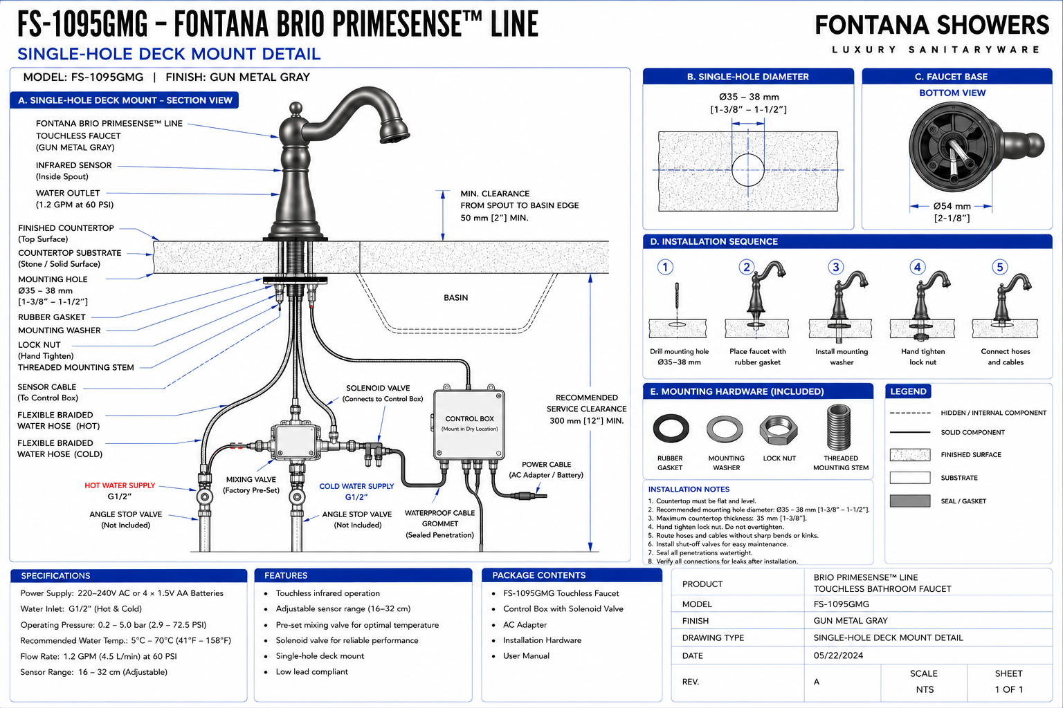
This single-hole deck-mount installation-detail resource is intended to support
architects, plumbing engineers, electrical engineers, interior designers,
countertop fabricators, millwork contractors, installers and facility managers
coordinating the Fontana Brio PrimeSense™ Line FS-1095GMG touchless bathroom
faucet within commercial and institutional washrooms. The drawing communicates
the relationship between the faucet body, single mounting opening, rubber gasket,
mounting washer, lock nut, threaded mounting stem, finished countertop,
countertop substrate, basin, braided water hoses, mixing valve, solenoid valve,
control box, sensor cable and power components.
.png)
Fontana Brio PrimeSense™ Line FS-1095GMG Touchless Bathroom Faucet
The Fontana FS-1095GMG is a single-hole deck-mounted touchless bathroom
faucet with a Gun Metal Gray finish and infrared automatic activation.
The faucet passes through a Ø35–38 mm countertop opening and is secured
below the deck with a rubber gasket, mounting washer and lock nut.
The concealed installation includes hot- and cold-water hoses, a factory
pre-set mixing valve, solenoid valve, sensor cable, electronic control box
and AC or battery power arrangement.
-
Model:
FS-1095GMG
-
Product type:
Touchless bathroom faucet
-
Installation:
Single-hole deck mount
-
Finish:
Gun Metal Gray
-
Operation:
Infrared touchless activation
-
Mounting-hole diameter:
Ø35–38 mm [1-3/8"–1-1/2"]
-
Faucet-base diameter:
Ø54 mm [2-1/8"]
-
Maximum countertop thickness:
35 mm [1-3/8"]
-
Water inlet:
G1/2" hot and cold
-
Operating pressure:
0.2–5.0 bar [2.9–72.5 PSI]
-
Flow rate:
1.2 GPM [4.5 L/min] at 60 PSI
-
Sensor range:
16–32 cm adjustable
-
Power supply:
220–240V AC or 4 × 1.5V AA batteries
-
Mixing:
Factory pre-set mixing valve
-
Recommended service clearance:
300 mm [12"] minimum
Required Single-Hole Deck Mount Drawing Package
The single-hole deck-mount drawing should clearly document the faucet
centerline, finished countertop, countertop substrate, Ø35–38 mm mounting
opening, Ø54 mm faucet base, rubber gasket, mounting washer, lock nut,
threaded mounting stem, sensor cable, braided hot- and cold-water hoses,
mixing valve, solenoid valve, electronic control box and power connections.
The relationship between the faucet outlet, basin and under-counter equipment
should be coordinated before countertop fabrication.
Complete Single-Hole Deck Mount Section
Shows the complete FS-1095GMG installation from the Gun Metal Gray
faucet above the countertop through the mounting hardware and
concealed plumbing and electronic system below. The section provides
the primary installation reference for countertop fabrication,
plumbing rough-in and final fixture mounting.
Single-Hole Mounting Opening
Provide a Ø35–38 mm [1-3/8"–1-1/2"] circular opening through
the countertop. The opening should be clean, centered on the approved
faucet location and coordinated with the basin and concealed
under-counter components.
Faucet Base Diameter
The faucet-base bottom view identifies an approximate Ø54 mm
[2-1/8"] footprint. The finished countertop should provide a
continuous flat bearing surface around the mounting opening so the
base and gasket can seat evenly.
Finished Countertop
Shows the finished stone, solid-surface or other approved deck
supporting the faucet. The mounting area should be flat and level
and should not contain seams or irregularities that prevent proper
gasket seating.
Countertop Substrate
Identifies the structural countertop material through which the
threaded mounting stem passes. Coordinate stone reinforcement,
plywood build-up and support members so they do not obstruct the
mounting washer or lock nut.
Maximum Countertop Thickness
The installation detail identifies approximately 35 mm [1-3/8"]
as the maximum countertop thickness. All finish, substrate and
reinforcement layers should be included when verifying mounting-stem
engagement.
Rubber Gasket
Shows the sealing gasket positioned between the faucet base and
countertop. The gasket should sit flat and concentric with the mounting
opening before the faucet is secured from below.
Mounting Washer
Identifies the underside washer installed over the threaded mounting
stem. The washer distributes the retaining load over the underside of
the countertop and contributes to stable faucet mounting.
Lock Nut
Shows the retaining nut threaded onto the faucet mounting stem below
the washer. Hand-tighten securely to prevent faucet movement while
avoiding excessive torque.
Threaded Mounting Stem
The threaded stem extends through the countertop opening and receives
the mounting washer and lock nut below the deck. It should remain
vertical and centered during tightening.
Faucet Centerline
Coordinate the mounting-hole centerline with the basin so the spout
outlet projects into the usable bowl area and the sensor remains
positioned for reliable hand detection.
Spout-to-Basin Clearance
The drawing identifies a minimum approximately 50 mm [2"]
clearance between the faucet spout and basin edge. Final positioning
should also consider basin geometry and splash control.
Infrared Sensor
The touchless sensor is integrated into the faucet assembly and
connects to the under-counter controller. Keep the sensor orientation
and basin relationship consistent with the approved installation
drawing.
Sensor Cable
Route the sensor cable from the faucet to the control box without
kinking, pinching or sharply bending the cable. Keep it clear of
moving cabinet hardware and plumbing connections.
Hot-Water Braided Hose
The hot-water hose connects the G1/2" hot-water angle stop to
the mixing assembly. Maintain a smooth routing radius and provide
access to both connection points.
Cold-Water Braided Hose
The cold-water hose connects the G1/2" cold-water angle stop to
the mixing valve. Do not twist, stretch or sharply bend the braided
connection.
Factory Pre-Set Mixing Valve
Shows the mixing valve receiving the hot- and cold-water supplies
and providing mixed water to the touchless faucet system. The valve
should remain accessible after cabinet completion.
Solenoid Valve
Identifies the electronically controlled water valve connected to the
control box. The solenoid responds to sensor commands to start and
stop faucet flow automatically.
Control Box
Mount the electronic control box in a dry and accessible location
below the countertop. Maintain access to cable connections, solenoid
wiring and power connections for commissioning and service.
Power Cable
The control system may be powered using the approved AC adapter or
battery configuration. Locate electrical components away from
potential water leakage and standing moisture.
Waterproof Cable Grommet
Where electrical cables pass through cabinet material or supporting
construction, provide the sealed cable penetration shown in the
drawing to protect the cable and limit moisture migration.
Angle Stop Valves
Provide separate accessible hot- and cold-water shutoff valves.
The angle stops are shown as project-supplied components and should
remain reachable for fixture isolation and maintenance.
Under-Counter Service Clearance
Maintain approximately 300 mm [12"] minimum recommended service
clearance beneath the countertop for access to hoses, valves,
controller connections and faucet mounting hardware.
Engineering note:
Do not release the countertop for fabrication based on nominal dimensions
alone. Confirm the Ø35–38 mm mounting-hole requirement, Ø54 mm faucet-base
footprint, maximum countertop thickness, mounting-hardware arrangement,
basin relationship, hose lengths, cable reach and required under-counter
service area using the approved FontanaShowers submittal and installation
documentation.
Single-Hole Mounting Detail
Ø35–38 mm Mounting Hole
Prepare a circular opening between Ø35 mm and Ø38 mm
[1-3/8"–1-1/2"] as identified in the deck-mount detail.
Ø54 mm Faucet Base
The faucet-base bottom view indicates an approximate Ø54 mm
[2-1/8"] footprint around the mounting stem and internal
connection area.
Centerline Coordination
Establish the faucet centerline before drilling so the spout,
basin and concealed plumbing equipment remain correctly aligned.
Flat Mounting Surface
The finished countertop must provide a flat and level mounting
surface for even gasket seating and stable faucet installation.
Maximum Deck Thickness
Coordinate the complete countertop build-up so the finished deck
thickness does not exceed the mounting capability shown in the
approved installation detail.
Under-Counter Accessibility
The mounting washer and lock nut must remain accessible beneath the
deck so the faucet can be tightened, inspected or removed without
damaging the countertop.
Recommended Single-Hole Installation Sequence
1. Drill the Mounting Hole
Mark the approved faucet centerline and prepare a Ø35–38 mm
[1-3/8"–1-1/2"] opening through the finished countertop.
Clean the opening before inserting the faucet.
2. Place Faucet with Rubber Gasket
Position the rubber gasket against the faucet base and lower the
threaded stem, hoses and sensor cable through the prepared mounting
opening.
3. Install Mounting Washer
From below the countertop, slide the mounting washer over the
threaded stem and position it flat against the countertop substrate.
4. Hand-Tighten Lock Nut
Thread the lock nut onto the mounting stem and tighten until the
faucet is secure. Confirm the faucet remains aligned with the basin
before final tightening.
5. Connect Hoses and Cables
Connect the hot- and cold-water hoses, mixing valve, solenoid valve,
sensor cable, control box and selected power source according to the
approved connection arrangement.
Mounting Hardware Identification
Rubber Gasket
Installed beneath the faucet base to provide a uniform seating surface
and help limit moisture penetration through the mounting opening.
Mounting Washer
Installed against the underside of the countertop to spread the
clamping force produced by the retaining nut.
Lock Nut
Threads onto the mounting stem and secures the faucet assembly to the
countertop. Tighten sufficiently to prevent fixture movement without
overloading the countertop.
Threaded Mounting Stem
Passes through the countertop and receives the washer and retaining
nut while providing a concealed route for faucet hoses and control
connections.
Architectural and Plumbing Coordination Considerations
Countertop Fabrication
Coordinate the Ø35–38 mm hole before fabrication and confirm that
countertop reinforcement, seams and sink clips will not obstruct the
mounting hardware.
Basin Coordination
Position the faucet so the water outlet directs flow into the usable
basin area while maintaining the minimum clearance indicated on the
drawing.
Millwork Coordination
Cabinet shelves, drawers, structural rails and partitions should not
block the mounting hardware, hoses, mixing valve, solenoid valve,
controller or service area.
Plumbing Coordination
Maintain access to the G1/2" hot- and cold-water angle stops,
mixing valve and solenoid connections for installation and future
maintenance.
Electrical Coordination
Locate the controller, power adapter or battery system in a dry,
accessible area and route control cables away from plumbing joints
and potential leakage points.
Maintenance Coordination
Provide sufficient working space beneath the countertop to access
the lock nut, braided hoses, valve assembly, control box and
electrical connectors.
Single-Hole Deck Mount Installation Notes
-
Countertop condition:
The countertop mounting area should be flat and level.
-
Mounting-hole diameter:
Provide Ø35–38 mm [1-3/8"–1-1/2"] as shown.
-
Maximum countertop thickness:
The drawing indicates approximately 35 mm [1-3/8"].
-
Rubber gasket:
Seat the gasket evenly beneath the faucet base before tightening the
mounting hardware.
-
Lock nut:
Hand-tighten securely and do not overtighten.
-
Hoses and cables:
Route connections without sharp bends, kinks or compression.
-
Isolation valves:
Install accessible hot- and cold-water shutoff valves for future
maintenance.
-
Waterproof penetrations:
Seal required cable and cabinet penetrations against moisture.
-
Leak testing:
Verify all hydraulic connections for leakage after the faucet is
installed and pressurized.
Technical Performance Information
Power Supply
220–240V AC or 4 × 1.5V AA batteries according to the project
power configuration.
Water Connections
G1/2" hot- and cold-water supply connections feed the
factory pre-set mixing assembly.
Operating Pressure
The drawing identifies an operating range of approximately
0.2–5.0 bar [2.9–72.5 PSI].
Recommended Water Temperature
The installation sheet indicates a recommended temperature range
of approximately 5°C–70°C [41°F–158°F].
Flow Rate
Nominal flow performance is identified as 1.2 GPM
[4.5 L/min] at 60 PSI.
Sensor Range
The infrared sensing range is identified as approximately
16–32 cm and is adjustable during commissioning.
Single-Hole Deck Mount Component Identification
-
Touchless faucet body:
Visible Gun Metal Gray faucet installed above the finished countertop.
-
Infrared sensor:
Detects hand presence and initiates automatic water flow.
-
Water outlet:
Delivers approximately 1.2 GPM at the referenced operating condition.
-
Rubber gasket:
Provides the sealing interface between faucet base and countertop.
-
Mounting washer:
Distributes retaining force below the countertop.
-
Lock nut:
Secures the faucet to the deck.
-
Threaded mounting stem:
Passes through the single mounting opening.
-
Hot-water braided hose:
Connects the hot-water supply to the mixing assembly.
-
Cold-water braided hose:
Connects the cold-water supply to the mixing assembly.
-
Mixing valve:
Combines hot and cold water before delivery to the automatic valve.
-
Solenoid valve:
Electronically controls water flow.
-
Sensor cable:
Connects the faucet sensor to the electronic controller.
-
Control box:
Processes sensor signals and operates the solenoid valve.
-
Power cable:
Connects the control system to the selected AC or battery supply.
-
Waterproof cable grommet:
Protects wiring at cabinet or enclosure penetrations.
-
Angle stop valves:
Provide independent hot- and cold-water isolation for maintenance.
FontanaShowers Installation and Specification Resources
FS-1095GMG Product Page
Product information and available technical documentation for the
Fontana Brio PrimeSense™ Gun Metal Gray touchless bathroom faucet.
FontanaShowers Installation Hub
Central installation information covering deck-mounted faucets,
touchless controls, plumbing connections and commissioning.
FS-1095GMG Single-Hole Mounting Coordination
Review current model information before establishing the mounting
opening, faucet centerline, countertop thickness and concealed
connection locations.
Touchless Faucet Installation Guidance
General guidance covering deck preparation, mounting hardware,
water-supply connections, electronic controls and commissioning.
Product Submittal Verification
Confirm current dimensions, mounting requirements, connection
details and power requirements before releasing fabrication
documents.
Touchless Bathroom Faucet Collection
Explore related Fontana automatic bathroom faucets for architectural,
commercial and institutional washroom projects.
Professional Engineering and Accessibility References
Project verification:
This single-hole deck-mount detail is intended for architectural,
plumbing, millwork and installation coordination and does not replace
approved manufacturer installation instructions or project submittals.
The architect, plumbing engineer, electrical engineer, countertop fabricator,
millwork contractor and licensed installer should verify the Ø35–38 mm
mounting opening, Ø54 mm faucet-base footprint, countertop thickness,
rubber gasket, mounting washer, lock nut, threaded mounting stem,
basin relationship, braided water hoses, mixing valve, solenoid valve,
control box, sensor cable, power configuration, service clearance,
accessibility requirements and locally adopted plumbing and electrical
codes before fabrication or installation.
|
|
|