Fontana Touchless Faucets™ | Architectural and Engineering Resource
Fontana Brio PrimeSense™ Line FS-1095GMG Gun Metal Gray Touchless Bathroom Faucet:
Countertop Hole & Clearance Drawing
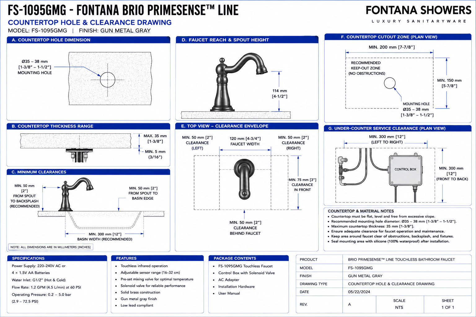
This countertop-hole and clearance drawing resource is intended to support
architects, plumbing engineers, interior designers, countertop fabricators,
millwork contractors, installers and facility managers coordinating the
Fontana Brio PrimeSense™ Line FS-1095GMG deck-mounted touchless bathroom
faucet. The drawing establishes the faucet mounting-hole location, countertop
centerline, faucet-base footprint, basin relationship, backsplash clearance,
counter-edge clearance, under-counter mounting envelope and service-access
area that should be confirmed before countertop fabrication.
Fontana Brio PrimeSense™ Line FS-1095GMG Touchless Bathroom Faucet
The Fontana FS-1095GMG is a solid-brass, single-hole, deck-mounted
touchless bathroom faucet designed for commercial and architectural
washrooms. Correct countertop preparation is critical because the
faucet mounting centerline determines the relationship between the
spout outlet, infrared sensing zone, basin capture area and concealed
under-counter mounting components.
-
Model:
FS-1095GMG
-
Product type:
Touchless bathroom faucet
-
Installation:
Deck mounted
-
Mounting:
Single hole
-
Finish:
Gun Metal Gray
-
Material:
Solid brass
-
Sensor range:
16–32 cm adjustable
-
Water connection:
G1/2"
-
Flow rate:
1.2 GPM [4.54 L/min] at 60 PSI
-
Power:
220–240V AC or DC 6V using 4 × AA batteries
-
Automatic safety shut-off:
30 seconds
-
Application:
Commercial and institutional washrooms
Required Countertop Hole & Clearance Drawing Package
The countertop drawing should show the faucet mounting centerline relative
to the lavatory basin, backsplash, finished counter edge and adjacent
fixtures. The mounting-hole diameter, faucet-base footprint, countertop
thickness, basin cutout, minimum edge clearances and under-counter access
zone should be documented before fabrication. Final dimensions should
always be confirmed against the approved FontanaShowers submittal.
Complete Countertop Hole & Clearance Drawing
Shows the complete countertop plan and section relationship between
the FS-1095GMG faucet, mounting hole, faucet base, basin opening,
backsplash, finished countertop edges and concealed under-counter
equipment zone.
Faucet Mounting Centerline
Establish the faucet mounting centerline before the countertop is
drilled. The centerline should position the water outlet within the
basin capture area while providing sufficient clearance from the
backsplash and basin edge.
Single Mounting Hole
Show the circular countertop opening required for the threaded faucet
shank, sensor cable and associated internal connections. Verify the
final diameter against the approved installation submittal before
drilling or CNC fabrication.
Hole Center Mark
The center of the mounting hole should be dimensioned from permanent
reference points such as the finished backsplash face, countertop
front edge or basin centerline rather than temporary construction
features.
Faucet-Base Footprint
Show the full footprint of the faucet base around the mounting hole.
The base should bear completely on the finished countertop and should
not overlap the basin opening, countertop seam or unsupported area.
Basin Edge Clearance
Maintain adequate horizontal separation between the mounting-hole
centerline and the basin edge so the faucet base remains fully
supported and the water stream enters the usable basin area.
Basin Cutout Clearance
Coordinate the faucet hole with the actual basin cutout rather than
only the visible bowl opening. Undermount basin flanges and support
rails can extend significantly beyond the finished opening.
Backsplash Clearance
Provide sufficient space behind the faucet body for installation,
cleaning and maintenance. The faucet should not contact the
backsplash or restrict installation access to the mounting hardware.
Front Counter-Edge Clearance
The faucet centerline should remain far enough from the front
countertop edge to preserve structural integrity while maintaining
the desired relationship between the outlet and basin.
Side Counter-Edge Clearance
Where the faucet is located near an end panel or narrow vanity,
provide sufficient lateral material around the mounting hole to
prevent cracking and maintain access to the underside mounting nut.
Countertop Seam Clearance
Do not position the mounting hole directly through a stone seam,
lamination joint or unsupported countertop transition unless
specifically approved by the countertop fabricator.
Countertop Thickness
Show the complete finished deck build-up including stone, solid
surface, substrate, reinforcement and any laminated layers. The
mounting stem must provide adequate engagement below the finished
deck.
Undermount Basin Flange
The concealed basin flange should be shown on the countertop plan
because it can interfere with the faucet washer, lock nut, hoses or
sensor cable even when it is not visible from above.
Basin Mounting Clips
Coordinate the faucet mounting zone with undermount sink clips,
brackets and adhesive anchors so they do not obstruct the faucet
shank or underside retaining hardware.
Countertop Reinforcement
Structural rails, plywood reinforcement and stone-support brackets
should not pass through the required faucet mounting zone or prevent
access to the lock nut.
Under-Counter Mounting Envelope
Show the area immediately below the mounting hole required for the
threaded stem, mounting washer, lock nut, flexible hoses and sensor
cable.
Under-Counter Equipment Clearance
Confirm that the basin, drain assembly, cabinet rails and shelves do
not occupy the space required by the faucet hoses, valve assembly,
controller and electrical connections.
Sensor Cable Drop Zone
Reserve an unobstructed path below the faucet for the sensor cable.
The cable should not be compressed between the basin, countertop
substrate or structural reinforcement.
Water-Hose Drop Zone
Provide a clear route beneath the faucet for the hot- and cold-water
connections without forcing the braided hoses around sharp sink edges
or structural supports.
Service Tool Clearance
Provide sufficient space around the underside mounting nut for hand
tightening, inspection and future removal of the faucet without
dismantling the lavatory.
Adjacent Fixture Clearance
Coordinate the faucet with soap dispensers, accessory holes and other
deck-mounted components so base plates do not overlap and concealed
components remain independently serviceable.
Finished Countertop Layout
The final shop drawing should show the complete coordinated
countertop after the basin, faucet, accessories, backsplash,
reinforcement and cabinet construction have been confirmed.
Engineering note:
Do not determine the faucet-hole location from the visible basin opening
alone. Coordinate the mounting centerline with the actual basin flange,
under-counter brackets, countertop reinforcement, cabinet framing,
backsplash and service requirements before drilling or CNC fabrication.
Required Countertop Drawing Views
Countertop Plan View
Show the faucet mounting hole, faucet-base footprint, basin cutout,
backsplash, countertop edges and adjacent fixture openings.
Mounting-Hole Detail
Provide an enlarged detail showing the mounting-hole diameter,
centerlines and dimensional references used by the countertop
fabricator.
Countertop Section
Show the finished countertop thickness, substrate and faucet
mounting stem extending below the deck.
Basin Relationship Section
Show the faucet outlet in relation to the basin rim, bowl depth and
water-stream landing area.
Under-Counter Plan View
Show the hidden basin flange, mounting clips, faucet shank, hoses,
controller, valves and structural supports.
Service-Clearance Detail
Show the clear area needed below and around the mounting hardware
for initial installation and future maintenance.
Countertop Fabrication Coordination
1. Confirm Final Basin Model
Verify the exact basin model and manufacturer cutout before locating
the faucet hole. Do not use generic basin dimensions for final
fabrication.
2. Establish Basin Centerline
Transfer the approved basin centerline to the countertop fabrication
drawing and use it as the primary horizontal reference for faucet
placement where appropriate.
3. Establish Faucet Centerline
Dimension the faucet centerline from permanent finished surfaces
and verify the water outlet will project into the desired basin
capture area.
4. Check Hidden Basin Components
Review the undermount flange, clips, rails and adhesive anchors
before confirming the final mounting-hole location.
5. Review Countertop Reinforcement
Confirm that support rails, steel brackets and plywood build-up do
not interfere with the faucet mounting stem or retaining hardware.
6. Verify Underside Access
Ensure the installer can reach the mounting washer, lock nut,
hoses and sensor cable from beneath the finished countertop.
7. Drill or CNC the Opening
Prepare the faucet opening only after the final approved dimensions
have been transferred to the countertop shop drawings.
8. Finish and Inspect the Hole
Remove sharp edges, chips or irregularities that could damage the
faucet gasket, hoses or sensor cable during installation.
Clearance Coordination Considerations
Basin Clearance
Provide sufficient distance from the basin opening to fully support
the faucet base and allow the water stream to enter the basin
without excessive splash.
Backsplash Clearance
Maintain sufficient space behind the faucet for cleaning,
installation and final alignment without contact with the backsplash.
Accessory Clearance
Coordinate soap dispensers and other deck accessories so their
mounting hardware does not conflict below the countertop.
Cabinet Clearance
Keep cabinet rails, drawers and partitions outside the faucet
mounting and service zone.
Drain Clearance
Coordinate the faucet hoses and electronic wiring with the lavatory
drain and trap so all systems remain independently accessible.
Electronic Component Clearance
Reserve sufficient dry space below the countertop for the control
box, motorized valve and power components required by the touchless
faucet system.
Countertop Hole & Clearance Installation Notes
-
Use approved dimensions:
Verify the final mounting-hole diameter against the approved
FontanaShowers installation submittal before countertop fabrication.
-
Flat mounting surface:
The faucet base should seat on a flat, level and structurally stable
finished countertop.
-
Avoid countertop seams:
Do not place the faucet opening directly over a stone seam or
unsupported joint without fabricator approval.
-
Verify basin flange:
Check the hidden undermount flange and mounting clips before finalizing
the faucet-hole location.
-
Maintain underside access:
The installer must be able to reach the mounting washer and lock nut
from below the deck.
-
Protect cables and hoses:
Remove sharp edges from the mounting opening and maintain clear routing
paths below the faucet.
-
Coordinate adjacent fixtures:
Prevent overlap between faucet, soap-dispenser and accessory mounting
hardware.
-
Confirm service access:
Do not allow drawers, shelves or cabinet framing to block the faucet
mounting zone.
-
Verify basin alignment:
Check the final water-stream location before releasing the countertop
for production.
Technical Performance Information
Touchless Operation
The Brio PrimeSense™ platform uses an adjustable infrared detection
range of approximately 16–32 cm for touch-free activation.
Flow Performance
The product page identifies a nominal flow rate of approximately
1.2 GPM [4.54 L/min] at 60 PSI.
Water Connection
The touchless faucet system uses G1/2" inlet and outlet
connections according to the current product specification.
Power Options
The faucet supports 220–240V AC operation or DC 6V battery
operation using four AA batteries.
Safety Shut-Off
The electronic control system provides an automatic approximately
30-second safety shut-off during extended activation.
Commercial Application
The deck-mounted faucet is designed for high-traffic commercial
washrooms including airports, hotels, healthcare facilities and
office buildings.
Countertop Drawing Component Identification
-
Faucet centerline:
Primary reference line establishing the faucet position relative to the
basin and countertop.
-
Mounting hole:
Circular countertop penetration receiving the faucet mounting stem.
-
Faucet base:
Visible deck-mounted footprint bearing on the finished countertop.
-
Finished countertop:
Exposed stone, solid-surface or approved architectural deck material.
-
Countertop substrate:
Structural support layer below the finished surface.
-
Basin cutout:
Countertop opening receiving the lavatory basin.
-
Undermount basin flange:
Hidden basin perimeter extending beneath the countertop.
-
Basin mounting clips:
Concealed hardware securing the basin to the underside of the deck.
-
Backsplash:
Rear finished surface used as a dimensional reference for faucet
placement.
-
Mounting stem:
Threaded component extending below the countertop.
-
Mounting washer:
Underside component distributing the faucet clamping load.
-
Lock nut:
Retaining hardware securing the faucet to the countertop.
-
Sensor cable:
Low-voltage cable connecting the faucet sensor to the control system.
-
Water hoses:
Flexible connections routed from the faucet mounting area to the
under-counter hydraulic components.
-
Service zone:
Clear working area required around the mounting and concealed control
components.
FontanaShowers Installation and Specification Resources
Professional Engineering and Accessibility References
Project verification:
This countertop-hole and clearance drawing is intended for architectural,
plumbing, millwork and fabrication coordination and does not replace approved
manufacturer installation instructions or project submittals. The architect,
plumbing engineer, countertop fabricator, millwork contractor and licensed
installer should verify the mounting-hole diameter, faucet-base footprint,
countertop thickness, mounting centerline, basin cutout, undermount basin
flange, mounting clips, backsplash clearance, countertop edge clearances,
under-counter mounting envelope, water-hose routing, sensor-cable routing,
service access and applicable project requirements before countertop
fabrication or installation.
|
|
|


.png)









