Fontana Touchless Faucets™ | Architectural and Engineering Resource
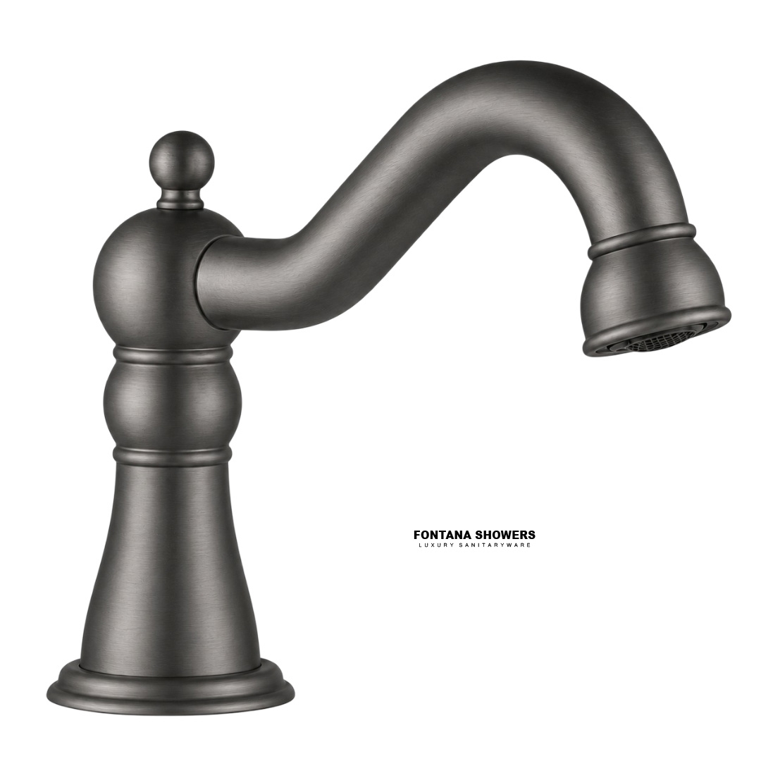
Fontana Brio PrimeSense™ Line FS-1095GMG Gun Metal Gray Touchless Bathroom Faucet:
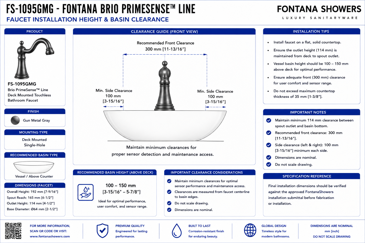
Faucet Installation Height & Basin Clearance
This faucet installation-height and basin-clearance drawing resource is intended
to support architects, plumbing engineers, interior designers, countertop
fabricators, millwork contractors, installers and facility managers coordinating
the Fontana Brio PrimeSense™ Line FS-1095GMG touchless bathroom faucet with a
commercial lavatory basin. The drawing establishes the relationship between the
finished countertop, faucet mounting plane, spout outlet, basin rim, basin
interior, water-stream landing area, infrared sensor zone, backsplash and
under-counter components so fixture placement can be coordinated before
countertop fabrication and final installation.
Fontana Brio PrimeSense™ Line FS-1095GMG Touchless Bathroom Faucet
The Fontana FS-1095GMG is a single-hole, deck-mounted automatic faucet
designed for touch-free commercial handwashing applications. Correct
installation height and basin coordination are important because the
faucet outlet, infrared sensing field and water-stream trajectory must
work together with the selected lavatory geometry to provide reliable
activation, comfortable hand clearance and controlled splash performance.
-
Model:
FS-1095GMG
-
Product type:
Touchless bathroom faucet
-
Installation:
Deck mounted
-
Mounting:
Single hole
-
Finish:
Gun Metal Gray
-
Operation:
Infrared sensor activation
-
Sensor range:
16–32 cm adjustable
-
Water connection:
G1/2"
-
Flow rate:
1.2 GPM [4.54 L/min] at 60 PSI
-
Temperature mixing:
Below-deck mixing arrangement
-
Automatic timeout:
30 seconds factory default
-
Application:
Commercial and institutional washrooms
Required Faucet Installation Height & Basin Clearance Drawing Package
The installation-height drawing should use the finished countertop as the
primary vertical reference plane and should clearly show the faucet body,
spout outlet, basin rim, basin interior, water-stream landing point,
sensor-detection field and backsplash. Vertical and horizontal clearances
should be coordinated with the actual basin selected for the project rather
than a generic lavatory profile. Final construction dimensions should be
verified against the approved FontanaShowers product submittal and actual
fixture samples where critical.
Complete Installation Height & Basin Clearance Elevation
Shows the complete relationship between the FS-1095GMG faucet,
finished countertop, basin rim, bowl interior and water-stream landing
area. The elevation should establish all relevant vertical heights and
horizontal clearances needed for coordinated fixture installation.
Finished Countertop Reference Plane
Use the top of the finished countertop as the primary elevation datum
for faucet mounting and height dimensions. Countertop substrate,
build-up and support layers should not be substituted for the finished
surface reference.
Faucet Overall Height
Show the vertical dimension from the finished countertop to the
highest point of the faucet body. This dimension assists architectural
coordination with mirrors, shelves, backsplash features and adjacent
washroom accessories.
Spout Outlet Height
Show the vertical distance from the finished countertop to the water
outlet. The outlet height should be coordinated with the basin rim
and bowl depth to provide adequate handwashing clearance while
limiting splash.
Spout Projection
Identify the horizontal projection from the faucet mounting centerline
to the center of the water outlet. The projection should place the
water stream within the basin’s effective capture area.
Basin Rim Elevation
Show the basin rim or countertop-basin transition relative to the
faucet outlet. Vessel, drop-in, integrated and undermount basins may
produce significantly different clearance conditions.
Outlet-to-Basin Rim Clearance
Provide sufficient vertical and horizontal clearance between the
faucet outlet and basin rim so users can comfortably place their
hands within the sensing and washing zone without contacting the
fixture or basin.
Spout-to-Basin Edge Clearance
Show the horizontal relationship between the outlet and nearest basin
edge. The clearance should prevent the water stream from striking the
rim while maintaining an effective hand-detection zone in front of
the sensor.
Basin Interior Depth
Identify the usable bowl depth below the rim or countertop plane.
Basin depth has a direct influence on splash performance and should
be evaluated together with faucet flow, outlet height and stream
trajectory.
Water-Stream Landing Point
Show the intended location where the faucet stream contacts the basin.
The stream should land within the central usable bowl area rather than
directly on the drain, steep sidewall or front rim.
Water-Stream Trajectory
Illustrate the expected path from the faucet outlet into the basin.
This provides a useful coordination reference when selecting basin
depth, drain location and mounting centerline.
Infrared Sensor Zone
Show the adjustable 16–32 cm detection field in relation to the
faucet outlet and basin. The sensor should recognize normal hand
movement without continuously detecting the basin itself.
Handwashing Activation Zone
Identify the practical hand position where the user enters the
infrared sensing field and receives water flow. The activation zone
should overlap naturally with the basin’s comfortable handwashing
area.
Sensor-to-Basin Clearance
Maintain sufficient separation between the sensor field and reflective
basin surfaces. Excessively close or highly reflective surfaces may
require sensor-range adjustment during commissioning.
Backsplash Clearance
Show the horizontal distance from the rear of the faucet to the
backsplash. Sufficient clearance should be provided for installation,
cleaning and maintenance without the faucet body contacting the wall
finish.
Mirror Clearance
Where mirrors extend close to the countertop, confirm that the faucet
height and projecting geometry do not conflict with mirror edges,
mirror frames or integrated shelving.
Basin Drain Relationship
Show the drain location relative to the faucet stream. Direct impact
onto a drain cover or pop-up assembly may increase splash and should
be reviewed during fixture coordination.
Front Basin Clearance
Maintain sufficient distance between the water-stream landing area and
the front basin wall so splash is contained within the bowl during
normal operation.
Rear Basin Clearance
Provide enough space between the mounting centerline and rear basin
wall to prevent the water stream or sensor field from interacting
adversely with the rear bowl surface.
Lateral Basin Alignment
The faucet centerline should generally coordinate with the intended
basin washing zone. Offset installations should be reviewed carefully
for water-stream capture and sensor performance.
User Hand Clearance
Provide adequate unobstructed space between the outlet and basin
interior so users can wash comfortably without contacting the faucet,
basin rim or drain assembly.
Splash-Control Envelope
Show the preferred basin area intended to contain the water stream
and normal handwashing splash. Faucet height, projection, flow rate
and basin geometry should be evaluated together.
Under-Counter Component Clearance
Confirm that the basin depth and mounting configuration leave
sufficient space below the countertop for the faucet shank, hoses,
mixing valve, control components and service access.
Final Coordinated Installation Envelope
The final drawing should combine faucet height, spout projection,
basin geometry, sensor range, water-stream trajectory and concealed
service requirements into one coordinated installation envelope.
Engineering note:
Do not establish faucet installation height or basin clearance using a
generic sink profile. Verify the actual basin rim elevation, bowl depth,
drain location, faucet outlet position and sensor relationship before
releasing countertop fabrication or plumbing coordination drawings.
Required Installation Height Drawing Views
Side Elevation
Show the faucet overall height, spout outlet height, countertop,
basin profile, water-stream path and backsplash relationship.
Front Elevation
Show the faucet centerline, basin centerline, lateral clearances and
relationship between the fixture and usable bowl width.
Basin Section
Show the basin rim, bowl depth, drain position and water-stream
landing area relative to the faucet outlet.
Sensor Detection Diagram
Show the adjustable sensor zone relative to normal hand position,
basin surfaces and water-stream location.
Countertop Plan View
Show the faucet centerline, basin opening, backsplash and horizontal
spout-to-basin relationship.
Under-Counter Section
Show basin depth, faucet mounting stem, hoses and concealed control
components to confirm adequate service clearance.
Faucet Height Coordination
Countertop Datum
Use the top finished surface of the countertop as the datum for all
vertical faucet dimensions and installation-height references.
Fixture Overall Height
Confirm the overall faucet height against mirrors, backsplash
features, shelves and wall-mounted accessories above the lavatory.
Outlet Elevation
Coordinate the water-outlet elevation with the actual basin rim
and depth rather than selecting the faucet location independently.
User Working Zone
The vertical space between the outlet and basin should provide a
natural working zone for handwashing without requiring contact with
the faucet or bowl.
Sensor Working Zone
The infrared detection field should overlap the user working zone
without remaining continuously activated by the basin surface.
Splash Performance
Higher outlet elevations can increase splash potential. Review the
combined faucet and basin geometry during fixture selection and
commissioning.
Basin Clearance Coordination
Spout Reach
The spout should extend sufficiently over the basin so water falls
within the usable bowl rather than onto the rear rim or countertop.
Basin Rim
The basin rim should remain clear of the faucet outlet, user hand
position and infrared detection path.
Bowl Depth
Deeper bowls generally provide greater splash containment, but
under-counter clearance for controls and plumbing should also be
considered.
Drain Position
Avoid aligning the water stream directly onto a raised drain fitting
where doing so could redirect water toward the user or countertop.
Rear Bowl Wall
The rear bowl surface should not be so close to the faucet that it
interferes with the sensor field or produces immediate splashback.
Front Bowl Wall
Maintain adequate distance between the stream landing point and front
bowl wall to contain normal handwashing splash within the basin.
Sensor and Basin Relationship
Adjustable Detection Range
The Fontana technical documentation identifies an adjustable infrared
detection zone of approximately 16–32 cm. Final sensor settings should
be established after the faucet and basin are installed.
Reflective Basin Surfaces
Highly reflective polished metal, glass or glossy ceramic surfaces
should be tested because reflected infrared energy can influence
automatic sensor behavior.
False Activation Prevention
Adjust the sensor so the empty basin does not remain continuously
within the detection field when no user is present.
Hand Detection
Confirm that hands approaching the normal wash area are detected
quickly without requiring the user to reach excessively close to the
basin or faucet.
Sensor-to-Stream Coordination
The sensor field should activate water while the user’s hands are
positioned naturally below or near the outlet stream.
Commissioning Test
Perform repeated activation tests from different approach angles after
the basin, countertop and surrounding finishes are fully installed.
Water-Stream & Splash-Control Coordination
Flow Rate
The current technical specification identifies approximately
1.2 GPM [4.54 L/min] at 60 PSI. Basin geometry should be selected
to manage the resulting stream effectively.
Stream Landing Zone
Position the faucet so the stream contacts a relatively flat or
gently curved section of the basin rather than a steep sidewall.
Drain Avoidance
Where practical, avoid direct impact on drain covers or raised
waste fittings that may redirect the water stream.
Outlet Height
Do not increase the outlet-to-basin distance unnecessarily because
greater fall height can increase water velocity at impact and splash.
Bowl Width
Ensure the basin provides adequate width around the stream landing
zone for hand movement while maintaining splash containment.
Field Verification
Test the installed faucet at normal operating pressure and adjust
available flow or sensor settings where required to achieve acceptable
splash performance.
Recommended Height & Clearance Coordination Sequence
1. Confirm Faucet Model
Verify the final FS-1095GMG model and approved technical submittal
before establishing installation geometry.
2. Confirm Basin Model
Obtain the exact basin dimensions, rim profile, depth, drain location
and mounting arrangement.
3. Establish Countertop Datum
Use the finished countertop plane as the common vertical reference
for faucet and basin coordination.
4. Position Faucet Centerline
Locate the faucet so the outlet projects into the desired basin
washing zone.
5. Check Vertical Clearance
Verify the distance between the outlet and basin rim provides
comfortable hand clearance without excessive stream drop.
6. Check Stream Landing Point
Confirm the projected stream lands inside the bowl and does not
strike the rim or drain assembly unfavorably.
7. Check Sensor Relationship
Confirm the basin will not remain within the active infrared
detection field during normal standby conditions.
8. Review Under-Counter Clearance
Verify that basin depth does not block the faucet mounting hardware,
hoses or touchless control components.
9. Release Countertop Fabrication
Finalize the faucet mounting-hole location only after all above-deck
and below-deck clearances have been coordinated.
10. Commission the Installed Fixture
Test sensor activation, water-stream alignment and splash containment
after installation and make permitted adjustments as required.
Faucet Installation Height & Basin Clearance Notes
-
Finished countertop datum:
Use the finished countertop surface as the vertical reference for
faucet-height dimensions.
-
Actual basin required:
Coordinate the faucet with the selected project basin rather than a
generic sink profile.
-
Spout projection:
The outlet should project into the usable basin area.
-
Vertical hand clearance:
Provide sufficient space below the outlet for comfortable touchless
handwashing.
-
Sensor range:
The technical documentation identifies an adjustable detection range of
approximately 16–32 cm.
-
Sensor interference:
Test reflective basin surfaces during commissioning and adjust the sensor
where required.
-
Stream landing:
Avoid directing the water stream onto the basin rim, steep sidewall or
raised drain fitting.
-
Splash control:
Coordinate faucet height, flow rate, spout reach and basin depth as one
system.
-
Backsplash clearance:
Provide enough clearance for installation, cleaning and future
maintenance.
-
Field commissioning:
Verify sensor response and basin splash performance after the complete
washroom finishes are installed.
Technical Performance Information
Detection Zone
The current FS-1095 technical specification identifies an adjustable
infrared detection zone of approximately 16–32 cm.
Flow Rate
Technical documentation identifies approximately 1.2 GPM
[4.54 L/min] at 60 PSI.
Water Connection
The faucet control system uses G1/2" inlet and outlet
connections.
Temperature Mixing
The current technical specification identifies a below-deck manual
mixing-valve arrangement.
Automatic Timeout
The electronic control system is specified with a factory-default
30-second timeout.
Response Performance
The FS-1095 technical documentation specifies automatic electronic
opening in less than approximately one second.
Installation Height Drawing Component Identification
-
Finished countertop:
Primary mounting and vertical-dimension reference plane.
-
Faucet body:
Visible Gun Metal Gray touchless fixture above the countertop.
-
Spout outlet:
Point from which the controlled water stream enters the basin.
-
Infrared sensor:
Detects user hand presence and initiates automatic operation.
-
Sensor zone:
Adjustable hand-detection region below and in front of the spout.
-
Basin rim:
Upper edge or transition line defining the entrance to the bowl.
-
Basin interior:
Usable handwashing and water-capture area.
-
Water-stream trajectory:
Path from the faucet outlet to the basin landing point.
-
Stream landing point:
Intended basin surface where the discharged water first contacts the
bowl.
-
Basin drain:
Waste outlet requiring coordination with the water-stream trajectory.
-
Backsplash:
Rear architectural surface requiring clearance from the faucet body.
-
Mounting centerline:
Primary horizontal location reference for faucet installation.
-
User working zone:
Clear space between faucet outlet and basin used during normal
handwashing.
-
Splash-control zone:
Basin region intended to contain stream impact and handwashing splash.
-
Under-counter service zone:
Space required for faucet mounting and concealed touchless components.
FontanaShowers Installation and Specification Resources
Professional Engineering and Accessibility References
Project verification:
This faucet installation-height and basin-clearance resource is intended for
architectural, plumbing, countertop and installation coordination and does not
replace approved manufacturer installation instructions or project submittals.
The architect, plumbing engineer, interior designer, countertop fabricator,
millwork contractor and licensed installer should verify the finished countertop
elevation, faucet mounting centerline, overall faucet height, spout outlet
height, spout projection, basin rim elevation, bowl depth, drain location,
water-stream landing point, sensor-detection relationship, backsplash clearance,
under-counter service zone, accessibility requirements and locally adopted
codes before fabrication or installation.
|
|
|