Fontana Touchless Faucets™ | Architectural and Engineering Resource
Fontana Brio PrimeSense™ Line FS-1095GMG Gun Metal Gray Touchless Bathroom Faucet:
Sensor Detection Zone & Calibration
This sensor-detection-zone and calibration resource is intended to support
architects, plumbing engineers, electrical engineers, interior designers,
contractors, installers, commissioning technicians and facility managers
coordinating the Fontana Brio PrimeSense™ Line FS-1095GMG touchless bathroom
faucet. The drawing and calibration notes establish the relationship between the
infrared sensor, adjustable detection field, handwashing activation zone, faucet
outlet, basin geometry, reflective surfaces, backsplash, control box, sensor
cable and commissioning procedures required for reliable automatic operation.
Fontana Brio PrimeSense™ Line FS-1095GMG Touchless Bathroom Faucet
The Fontana FS-1095GMG uses infrared sensing to initiate automatic
water flow when a user’s hands enter the calibrated detection field.
Correct sensor adjustment is essential because basin depth, reflective
finishes, faucet position, countertop geometry and surrounding fixtures
can influence the effective sensing zone and automatic shut-off response.
-
Model:
FS-1095GMG
-
Product type:
Touchless bathroom faucet
-
Installation:
Single-hole deck mount
-
Finish:
Gun Metal Gray
-
Sensor type:
Infrared touchless activation
-
Sensor location:
Integrated within faucet / spout assembly
-
Detection range:
Approximately 16–32 cm adjustable
-
Flow rate:
1.2 GPM [4.5 L/min] at 60 PSI
-
Water connection:
G1/2"
-
Control:
Electronic control box and solenoid valve
-
Power:
AC or battery configuration
-
Application:
Commercial and institutional washrooms
Required Sensor Detection Zone & Calibration Drawing Package
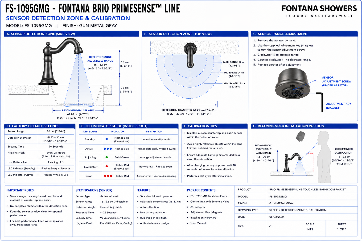
The sensor-calibration drawing should show the faucet in side elevation and
identify the infrared sensing point, normal user hand position, minimum and
maximum detection limits, basin rim, basin interior, water-stream path,
backsplash, reflective surfaces and under-counter control components. The
drawing should make clear that final sensor settings are established after
the faucet, basin, countertop and surrounding finishes are completely
installed.
Complete Sensor Detection Zone & Calibration Detail
Shows the complete FS-1095GMG sensing relationship from the infrared
sensor within the faucet to the user hand-detection field below the
spout. The drawing should identify the basin, stream path, adjustable
sensor range, control box, sensor cable and potential interference
zones.
Infrared Sensor Location
Identify the infrared sensing element integrated into the faucet
assembly. The sensor should remain unobstructed and correctly oriented
toward the intended handwashing area.
Adjustable Detection Range
Show the approximate adjustable sensing envelope of 16–32 cm. Final
range should be established during commissioning based on the actual
basin geometry and surrounding finish conditions.
Minimum Detection Boundary
Identify the nearest practical hand position that should activate the
faucet. The minimum zone should not require users to place their hands
uncomfortably close to the faucet body or basin surface.
Maximum Detection Boundary
Show the outer sensor limit beyond which hand movement should not
activate the faucet. Excessive sensor range can increase the potential
for unintended activation by nearby users or reflective surfaces.
Primary Handwashing Zone
Identify the central area below the outlet where users naturally place
their hands for washing. The sensor field should overlap this region
consistently without requiring unusual hand positioning.
Activation Approach Zone
Show the path by which hands enter the detection field from the front
of the basin. The faucet should activate promptly as the user reaches
the normal washing position.
Deactivation Zone
Identify the point at which hands leave the sensing field and the
controller commands the solenoid valve to close. The shut-off response
should be confirmed during final commissioning.
Basin Reflection Zone
Highlight portions of the basin that may reflect infrared energy back
toward the sensor. Highly polished or glossy basin finishes should be
evaluated carefully during calibration.
Rear Basin Interference
Check the rear bowl wall to confirm it does not remain permanently
within the active sensing zone. A sensor range that is too long may
cause persistent or intermittent activation.
Front Basin Interference
Confirm the sensor does not extend unnecessarily toward the front rim
or beyond the usable basin area where passing objects may trigger the
faucet unintentionally.
Water-Stream Relationship
The sensor field should activate the faucet while the user's hands are
positioned naturally within or immediately adjacent to the water
stream.
Spout Outlet Relationship
Show the sensor zone relative to the faucet outlet so activation
occurs before or as the user's hands enter the primary water-stream
area.
Backsplash Interference Zone
Confirm the backsplash or rear wall finish does not fall within an
unwanted sensor path, particularly where polished stone, glass or
metal finishes are used.
Mirror Reflection Consideration
Where mirrors extend close to the countertop, review their proximity
and reflectivity during commissioning to ensure they do not affect
sensor performance.
Adjacent Faucet Interference
In multi-station lavatories, verify that the sensor field of one
faucet does not overlap the normal operating zone of the adjacent
faucet.
Adjacent Soap Dispenser Clearance
Deck-mounted soap dispensers and other accessories should remain
outside the primary sensor field so normal accessory use does not
trigger unintended faucet activation.
Sensor Cable Route
Show the sensor cable from the faucet to the control box. Keep the
cable protected from sharp bends, crushing, cabinet hardware and
moisture exposure.
Control Box Location
The electronic controller should be mounted in a dry and accessible
under-counter location where sensor connections can be inspected and
calibration-related servicing can be performed.
Solenoid Response
The drawing should identify the control relationship between the
sensor, electronic controller and solenoid valve. Reliable sensor
input should produce immediate and repeatable valve operation.
Standby Zone
Show the basin condition when no user is present. In standby, no
permanent surface should remain inside the active detection field.
False-Trigger Exclusion Zone
Identify areas where moving doors, cleaning tools, waste bins,
accessories or nearby traffic could unintentionally enter the sensor
field.
Calibration Verification Zone
After adjustment, test multiple hand positions within the intended
wash area and confirm that activation is consistent throughout the
usable sensor field.
Final Calibrated Detection Envelope
The final drawing should document the approved field-adjusted sensor
envelope after the faucet, basin and surrounding surfaces have been
fully commissioned.
Engineering note:
Sensor range should not be finalized before the basin, countertop,
backsplash and surrounding reflective finishes are installed. The
approximately 16–32 cm adjustment capability should be treated as a
commissioning range rather than a fixed project dimension.
Required Sensor Calibration Drawing Views
Side Sensor Elevation
Show the faucet, sensor, basin profile, minimum and maximum sensing
limits and normal handwashing position.
Front Sensor Elevation
Show the lateral width of the intended activation zone relative to the
basin centerline and adjacent fixtures.
Plan Detection View
Show the sensor field projected over the basin and identify any
adjacent fixture or accessory interference zones.
Basin Reflection Diagram
Show reflective basin surfaces and identify areas requiring attention
during final sensor calibration.
Control Connection Diagram
Show the infrared sensor, sensor cable, electronic control box,
solenoid valve and selected power source.
Commissioning Test Diagram
Show representative hand positions used to verify activation,
deactivation, side approach and false-trigger performance.
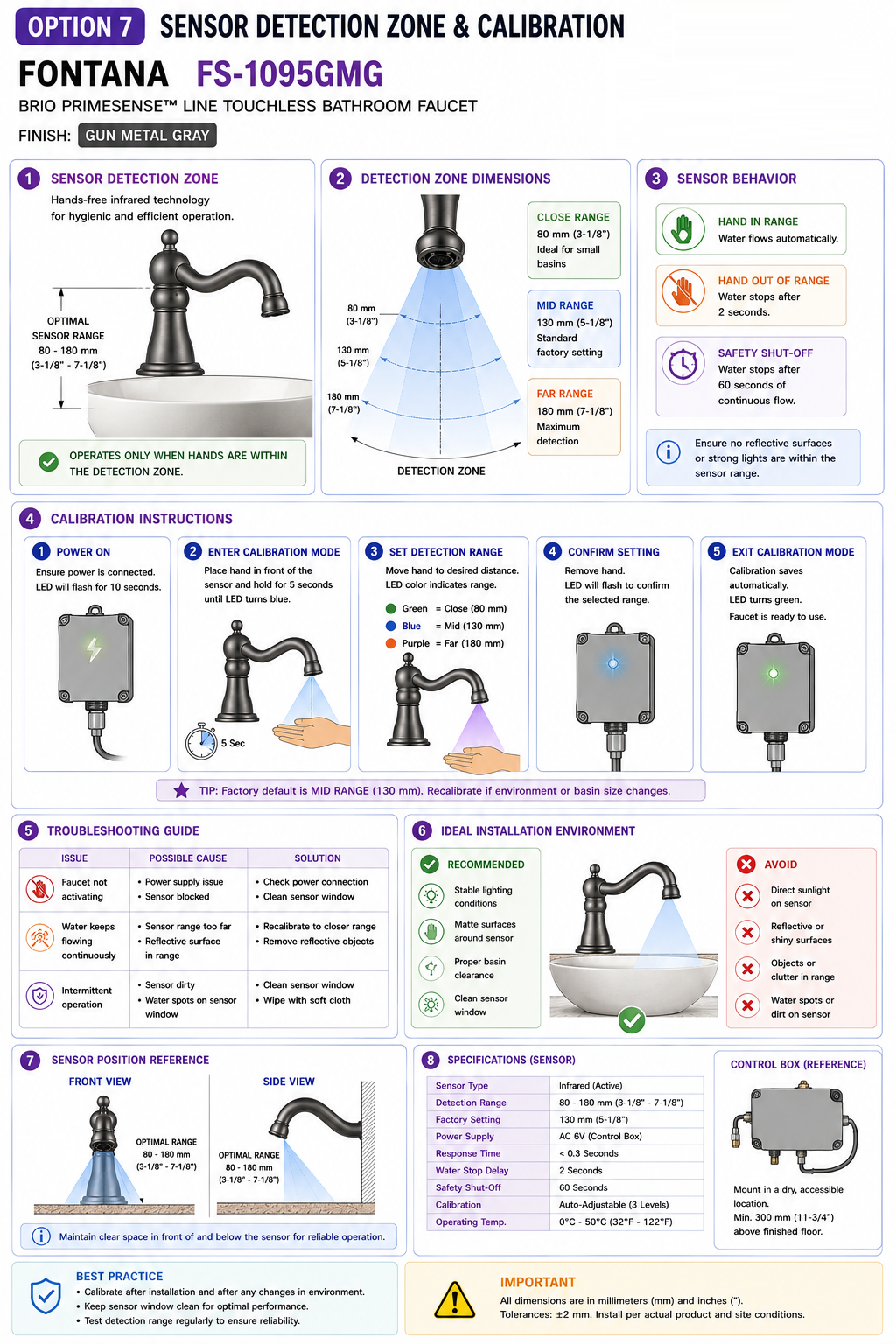
Recommended Sensor Calibration Sequence
1. Complete Mechanical Installation
Install and secure the faucet, water connections, solenoid valve and
controller before attempting final sensor calibration.
2. Complete Basin Installation
Ensure the final basin, countertop, drain and backsplash are installed
because these surfaces directly influence sensor behavior.
3. Energize the Control System
Connect the approved AC or battery power source and verify the
electronic controller and solenoid valve are operational.
4. Establish Initial Sensor Range
Set the sensor to a moderate starting distance within the available
adjustment range rather than immediately selecting the maximum reach.
5. Test Normal Hand Approach
Move hands naturally toward the wash area and confirm the faucet
activates before the user reaches an uncomfortable position.
6. Test Basin Standby Condition
Remove all hands and objects and verify the faucet remains off while
the empty basin is within its normal installed position.
7. Test Side Approaches
Approach from the left and right edges of the usable wash zone and
verify activation is consistent without an excessively wide field.
8. Test Reflective Surfaces
Observe operation with the final basin, countertop, backsplash and
mirror finishes in place and adjust range if reflections cause
unstable operation.
9. Verify Automatic Shut-Off
Remove hands from the field and confirm water stops promptly and
reliably after the user leaves the detection zone.
10. Record Final Calibration
Document the final approved sensor condition for commissioning
records and facility-maintenance reference.
Sensor Calibration Considerations
Sensor Range Too Short
If the sensing field is too short, users may need to move their hands
uncomfortably close to the faucet or basin before water begins to flow.
Sensor Range Too Long
Excessive range may allow the basin, passing users or nearby
accessories to enter the sensing field and produce unintended
activation.
Reflective Basin Finish
Glossy ceramic, polished metal, glass or highly reflective solid
surface may alter infrared behavior and should be tested under actual
installed lighting conditions.
Ambient Lighting
Complete final calibration with the washroom lighting system operating
in its normal occupied condition.
Adjacent Sensor Fixtures
In multi-user washrooms, verify nearby sensor faucets and automatic
soap dispensers do not create overlapping operating zones.
Cleaning Operations
Consider normal cleaning procedures so cloths, spray equipment or
maintenance tools do not routinely trigger the faucet unnecessarily.
False Activation Troubleshooting
Faucet Runs Without User
Check whether the basin, backsplash or nearby object is continuously
inside the detection field. Reduce or recalibrate sensor range where
appropriate.
Intermittent Activation
Inspect for reflective surfaces, unstable sensor connections, moving
objects or nearby automatic fixtures influencing the sensing area.
Delayed Activation
Verify the handwashing position falls within the calibrated field and
confirm the sensor lens is clean and unobstructed.
No Activation
Confirm power, sensor-cable connections, controller operation and
sensing distance before replacing components.
Continuous Water Flow
Determine whether the sensor is continuously detecting a surface or
whether the issue is associated with the controller or solenoid valve.
Inconsistent Side Detection
Check faucet alignment and verify that the sensor field is centered
over the intended handwashing area.
Sensor Detection Zone & Calibration Notes
-
Final calibration:
Perform final sensor adjustment only after the basin, countertop,
backsplash and surrounding finishes are complete.
-
Detection range:
The sensor is intended to operate within an adjustable range of
approximately 16–32 cm.
-
Avoid maximum range by default:
Use only the sensing distance required for comfortable handwashing and
reliable activation.
-
Empty-basin test:
With no user present, verify that the basin itself does not activate the
faucet.
-
Reflective surfaces:
Test polished and glossy surfaces for sensor interference.
-
Sensor lens:
Keep the infrared sensing surface clean and free from soap residue,
mineral deposits and construction debris.
-
Sensor cable:
Verify connectors are fully seated and wiring is not pinched or damaged.
-
Controller location:
Keep the control box dry, accessible and protected from direct leakage.
-
Multi-fixture installations:
Check sensor interaction between adjacent faucets and automatic
accessories.
-
Commissioning record:
Document the final field-adjusted operating condition for future
maintenance.
Sensor System Component Identification
-
Infrared sensor:
Detects user hand presence and initiates faucet operation.
-
Detection field:
Adjustable sensing envelope extending into the handwashing zone.
-
Sensor lens:
Visible sensing surface that should remain clean and unobstructed.
-
Sensor cable:
Transfers the detection signal from the faucet to the electronic
controller.
-
Electronic control box:
Processes sensor input and commands the solenoid valve.
-
Solenoid valve:
Opens and closes the water supply in response to controller commands.
-
Power supply:
Provides electrical power through the approved AC or battery
configuration.
-
Handwashing zone:
Intended user area where sensor activation and water flow overlap.
-
Basin reflection zone:
Surface area that may influence sensor response through reflected
infrared energy.
-
Standby zone:
Condition where no user or permanent surface should trigger water flow.
FontanaShowers Installation and Specification Resources
Professional Engineering and Accessibility References
Project verification:
This sensor-detection-zone and calibration resource is intended for
architectural, plumbing, electrical, commissioning and maintenance coordination
and does not replace approved manufacturer installation instructions or project
submittals. The architect, plumbing engineer, electrical engineer, installer,
commissioning technician and facility manager should verify the infrared sensor
location, adjustable detection range, basin relationship, reflective surfaces,
backsplash conditions, adjacent fixtures, sensor cable, electronic controller,
solenoid valve, power configuration, activation response, shut-off performance
and final field-calibrated operating condition before project turnover.
|
|
|