Fontana Touchless Faucets™ | Architectural and Engineering Resource
Fontana Brio PrimeSense™ Line FS-1095GMG Gun Metal Gray Touchless Bathroom Faucet:
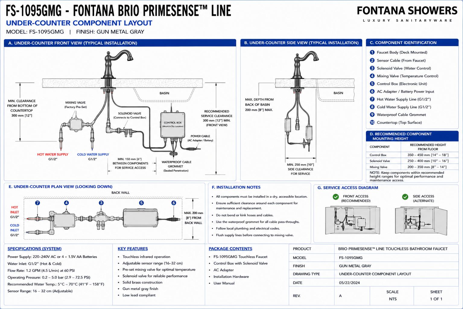
Under-Counter Component Layout
This under-counter component-layout resource is intended to support architects,
plumbing engineers, electrical engineers, interior designers, millwork
fabricators, contractors, installers and facility managers coordinating the
Fontana Brio PrimeSense™ Line FS-1095GMG touchless bathroom faucet. The layout
identifies the concealed relationship between the faucet mounting stem, sensor
cable, braided hot- and cold-water hoses, mixing valve, solenoid valve,
electronic control box, power cable, waterproof cable grommet, shutoff valves,
basin, drain assembly and required maintenance-access zone beneath the finished
countertop.
Fontana Brio PrimeSense™ Line FS-1095GMG Touchless Bathroom Faucet
The Fontana FS-1095GMG uses a concealed under-counter control system
that combines the faucet mounting hardware, hot- and cold-water
connections, temperature mixing components, electronically controlled
solenoid valve, sensor wiring, control box and power supply. Correct
component placement is important for reliable operation, leak inspection,
electrical protection and future maintenance access.
-
Model:
FS-1095GMG
-
Product type:
Touchless bathroom faucet
-
Installation:
Single-hole deck mount
-
Finish:
Gun Metal Gray
-
Water supply:
Hot and cold
-
Water connection:
G1/2"
-
Control:
Electronic control box and solenoid valve
-
Sensor:
Infrared touchless operation
-
Sensor range:
Approximately 16–32 cm adjustable
-
Flow rate:
1.2 GPM [4.5 L/min] at 60 PSI
-
Mixing:
Factory pre-set under-counter mixing valve
-
Power:
AC or battery configuration
-
Recommended service clearance:
300 mm [12"] minimum
-
Application:
Commercial and institutional washrooms
Required Under-Counter Component Layout Drawing Package
The under-counter drawing should present the concealed equipment below the
finished countertop in both elevation and plan. The drawing should identify
the faucet mounting stem, mounting washer, lock nut, sensor cable, hot- and
cold-water hoses, factory pre-set mixing valve, solenoid valve, control box,
power connection, waterproof cable penetration, angle stop valves, basin,
drain and required service-access envelope. Components should be arranged so
that each device can be inspected, disconnected and replaced without removing
the lavatory or permanent countertop.
Complete Under-Counter Component Layout
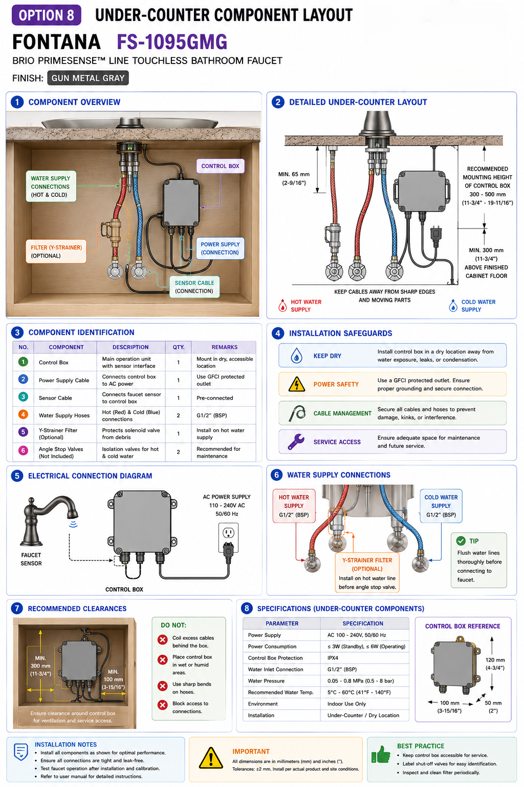
Shows the complete concealed installation below the FS-1095GMG faucet,
including the mounting stem, hot- and cold-water supplies, mixing
valve, solenoid valve, electronic controller, sensor cable, power
connection and service-access zone.
Faucet Mounting Stem
Show the threaded mounting stem immediately below the countertop.
The stem should remain accessible for inspection and should not be
blocked by the basin, structural rails or permanent cabinet elements.
Mounting Washer
Identify the mounting washer located against the underside of the
countertop. Maintain enough working room around the washer for
installation and future faucet removal.
Lock Nut
Show the retaining lock nut threaded onto the faucet stem. The nut
should remain reachable by hand or appropriate installation tools
without removing unrelated plumbing.
Sensor Cable Drop
Show the sensor cable descending from the faucet assembly to the
control box. Route the cable in a smooth path and keep it clear of
sharp metal edges, cabinet hinges and plumbing joints.
Hot-Water Braided Hose
Identify the braided hot-water hose from the G1/2" hot-water
angle stop to the mixing assembly. The hose should remain free of
kinks, twisting and excessive tension.
Cold-Water Braided Hose
Show the braided cold-water hose from the G1/2" cold-water angle
stop to the mixing valve. Maintain a direct routing path with service
access at both connections.
Hot-Water Angle Stop
Provide an accessible hot-water shutoff below the lavatory. The
valve should be reachable without removing the control box or other
faucet components.
Cold-Water Angle Stop
Provide an accessible cold-water isolation valve serving the faucet.
The shutoff location should allow independent fixture maintenance.
Factory Pre-Set Mixing Valve
Show the mixing valve receiving the hot- and cold-water supplies.
The valve should be positioned where its connections can be inspected,
adjusted if permitted and replaced without disturbing the basin.
Mixing Valve Support
The mixing assembly should not hang unsupported from flexible hoses.
Provide a stable installation arrangement that avoids transferring
excessive loads to fittings or braided connections.
Solenoid Valve
Identify the electronically controlled valve installed downstream of
the mixing assembly. The valve should be accessible for inspection,
cleaning and replacement.
Solenoid Flow Direction
Show the intended direction of water flow through the automatic valve
assembly. Verify inlet and outlet orientation before the water supply
is pressurized.
Valve-to-Faucet Connection
Show the flexible water connection between the automatic valve and
faucet inlet. Maintain smooth routing and avoid contact with the basin
or drain.
Electronic Control Box
Mount the control box in a dry, stable and accessible location.
The enclosure should remain above the lowest cabinet level where
practical and away from water-supply joints.
Controller Mounting Plane
Provide a suitable cabinet wall, support panel or mounting surface
for the controller. Do not leave the control box loose on the
cabinet floor.
Sensor-to-Controller Connection
Identify the low-voltage connection between the faucet sensor cable
and electronic controller. Keep connectors dry and accessible for
diagnostic testing.
Controller-to-Solenoid Cable
Show the electrical cable between the control box and solenoid valve.
The cable should be supported and routed away from water joints and
moving cabinet hardware.
AC Power Adapter
Where AC operation is selected, show the approved power adapter and
electrical connection in a dry and accessible location separated from
possible leakage points.
Battery Power Location
Where battery operation is selected, position the battery enclosure
so batteries can be replaced without dismantling plumbing or removing
the basin.
Power Cable Route
Show the power cable between the controller and selected power
source. Avoid routing electrical cables directly below water-supply
connections.
Waterproof Cable Grommet
Show any sealed cabinet penetration required for sensor or power
wiring. Use a suitable grommet or protected opening to prevent cable
damage and reduce moisture migration.
Basin Envelope
Show the complete underside profile of the basin because the bowl
depth can substantially reduce available space for the faucet
controller, valves and hoses.
Drain and Trap Envelope
Identify the lavatory drain and trap in relation to the touchless
faucet components. Maintain independent access to drainage fittings
and electronic equipment.
Drain Separation
Do not support electrical cables, controllers or water hoses on the
drain assembly. Maintain physical separation between the faucet
system and drainage piping.
Cabinet Floor Clearance
Mount electronic components above the lowest cabinet level where
practical to reduce exposure to cleaning water, condensation and
minor plumbing leaks.
Front Service Access
Provide an unobstructed front access path to the mixing valve,
solenoid valve, controller, power components and shutoff valves.
Minimum Service Clearance
Maintain approximately 300 mm [12"] minimum recommended working
clearance within the concealed equipment area where shown in the
installation layout.
Component Removal Path
Show how the control box, valve assemblies and power components can
be removed through the cabinet opening without removing permanent
millwork.
Finished Under-Counter Arrangement
The final installation should keep hoses, valves, cables and
electronics organized and separated so facility technicians can
identify each component quickly during maintenance.
Engineering note:
The under-counter layout should be coordinated after the actual basin,
drain, cabinet framing and faucet mounting position are known. Do not locate
the controller, solenoid valve or mixing valve using an empty-cabinet
assumption. Verify cable reach, hose length, drainage clearances and service
access before permanent cabinet panels or shelves are installed.
Required Under-Counter Drawing Views
Front Cabinet Elevation
Show the basin, faucet stem, hot and cold supplies, mixing valve,
solenoid valve, control box, power source and front access zone.
Side Cabinet Section
Show the basin depth, mounting hardware, hoses, controller depth
and available service space below the countertop.
Under-Counter Plan
Show the basin footprint, trap, angle stops, mixing valve, solenoid
valve, controller and all cable and hose routes.
Hydraulic Connection Diagram
Show hot and cold supplies, angle stops, mixing valve, solenoid valve
and faucet connection in the correct sequence.
Electrical Connection Diagram
Show the infrared sensor, controller, solenoid valve, AC adapter or
battery box and wiring connections.
Service Access Diagram
Show the minimum working area and removal path required for each
concealed service component.
Recommended Under-Counter Installation Sequence
1. Confirm Basin Envelope
Verify the final basin depth, drain position and underside support
before locating faucet-control equipment.
2. Confirm Water Supplies
Locate accessible G1/2" hot- and cold-water isolation valves
within reach of the approved braided hoses.
3. Reserve the Equipment Zone
Set aside a dedicated cabinet area for the mixing valve, solenoid
valve, controller and power components.
4. Mount the Mixing Valve
Install the mixing assembly in a stable position with clear access
to the hot, cold and mixed-water connections.
5. Install the Solenoid Valve
Install the automatic valve in the approved water-flow direction and
maintain adequate clearance for future service.
6. Mount the Control Box
Fasten the electronic controller to a dry cabinet surface above areas
likely to collect water.
7. Route Sensor Wiring
Connect the faucet sensor to the controller using a protected,
supported cable path.
8. Route Valve Wiring
Connect the solenoid valve to the controller and keep electrical
connections away from water joints.
9. Connect Power
Install the approved AC adapter or battery arrangement in an
accessible dry location.
10. Route Water Hoses
Connect hot, cold and mixed-water hoses without sharp bends,
twisting or unsupported loops.
11. Flush and Pressure Test
Flush the water supply before final connection and inspect all
hydraulic joints for leakage.
12. Verify Service Access
Confirm all valves, connectors, mounting hardware and electronic
components remain reachable before cabinet completion.
Hydraulic Component Coordination
Hot Supply
Connect the hot-water supply to the designated mixing-valve inlet
through an accessible shutoff valve.
Cold Supply
Connect the cold-water supply to the corresponding mixing-valve inlet
and preserve access to the isolation valve.
Mixed-Water Outlet
Route the mixed-water outlet toward the solenoid valve in accordance
with the approved hydraulic connection sequence.
Solenoid Connection
Maintain serviceable union or hose connections around the automatic
valve where provided by the installation arrangement.
Hose Bend Radius
Avoid tight bends immediately adjacent to hose fittings. Provide
gentle curves to reduce stress and maintain unrestricted water flow.
Leak Inspection Zone
Keep all water connections visible enough for inspection during
commissioning and periodic maintenance.
Electrical & Control Component Coordination
Sensor Connection
Connect the faucet sensor to the designated controller input and
secure excess cable without creating tight coils or strain.
Solenoid Connection
Connect the automatic valve to the designated control output and
maintain access to the electrical connector.
Controller Protection
Position the controller away from the trap, water-supply unions and
cabinet areas subject to cleaning water.
AC Power Location
Where AC power is used, coordinate the adapter and receptacle with the
project electrical requirements and maintain dry service access.
Battery Access
Where battery operation is selected, make sure the battery enclosure
can be opened and serviced without disconnecting plumbing.
Cable Separation
Keep low-voltage and power wiring organized and separated from hot
water piping, sharp metal edges and moving cabinet hardware.
Cabinet & Millwork Coordination
Sink Bowl Clearance
The basin should not press against hoses, sensor wiring or controller
connections after final installation.
Drawer Clearance
Drawer boxes and slides should remain outside the faucet equipment
zone and must not contact hoses or wiring during operation.
Shelf Clearance
Fixed shelves should not block shutoff valves, the controller,
mixing valve or solenoid valve.
Structural Rail Clearance
Coordinate cabinet rails and countertop supports with the faucet
mounting stem and service-access zone.
Removable Access Panel
Where concealed cabinetry limits normal access, provide a removable
panel sized for inspection and component replacement.
Service Door Swing
Cabinet doors should open sufficiently to allow technicians to reach
all concealed faucet components.
Under-Counter Component Layout Notes
-
Dry electronics zone:
Mount the controller and power components away from plumbing joints and
potential leak points.
-
Accessible shutoff valves:
Hot- and cold-water angle stops should remain immediately reachable for
maintenance.
-
Component support:
Do not allow valves or controllers to hang unsupported from hoses or
electrical cables.
-
Hose routing:
Keep braided water connections free from sharp bends, crushing and
twisting.
-
Cable routing:
Keep sensor and power wiring away from cabinet hinges, drawer slides and
sharp edges.
-
Drain separation:
Do not place the controller or electrical connectors directly below the
trap or drainage joints.
-
Cabinet floor:
Raise electrical components above areas where cleaning water or leaks may
accumulate.
-
Service clearance:
Maintain approximately 300 mm [12"] minimum recommended clearance
where required for component servicing.
-
Leak testing:
Inspect all hydraulic connections before energizing and commissioning the
system.
-
Final organization:
Label and secure hoses and wiring so future facility technicians can
identify system components quickly.
Under-Counter Component Identification
-
Threaded faucet stem:
Passes through the countertop and supports the faucet mounting assembly.
-
Mounting washer:
Distributes retaining pressure below the countertop.
-
Lock nut:
Secures the faucet to the finished deck.
-
Sensor cable:
Connects the infrared sensor to the electronic controller.
-
Hot-water hose:
Transfers hot water from the angle stop to the mixing valve.
-
Cold-water hose:
Transfers cold water from the angle stop to the mixing valve.
-
Mixing valve:
Combines hot and cold water before automatic flow control.
-
Solenoid valve:
Automatically opens and closes the mixed-water supply.
-
Electronic control box:
Processes sensor signals and controls the automatic valve.
-
Solenoid cable:
Connects the automatic valve to the controller.
-
AC adapter:
Provides electrical power where AC operation is selected.
-
Battery enclosure:
Provides battery power where the battery configuration is selected.
-
Power cable:
Transfers power to the electronic controller.
-
Waterproof cable grommet:
Protects electrical wiring at cabinet penetrations.
-
Angle stop valves:
Provide independent hot- and cold-water isolation.
-
Service zone:
Reserved area allowing component inspection, disconnection and
replacement.
FontanaShowers Installation and Specification Resources
Professional Engineering and Accessibility References
Project verification:
This under-counter component-layout resource is intended for architectural,
plumbing, electrical, millwork and installation coordination and does not
replace approved manufacturer instructions or project submittals. The architect,
plumbing engineer, electrical engineer, millwork fabricator, licensed installer
and facility manager should verify the faucet mounting stem, basin envelope,
drain assembly, hot- and cold-water supplies, mixing valve, solenoid valve,
control box, sensor cable, power configuration, waterproof cable penetrations,
service-clearance zone, component removal paths and locally adopted plumbing
and electrical requirements before final installation.
|
|
|