Fontana Touchless Faucets™ | Architectural and Engineering Resource
Fontana Brio PrimeSense™ Line FS-1095GMG Gun Metal Gray Touchless Bathroom Faucet:
G1/2 Water Supply Connection Detail
This G1/2 water-supply connection-detail resource is intended to support
architects, plumbing engineers, mechanical contractors, installers, millwork
fabricators and facility managers coordinating the Fontana Brio PrimeSense™
Line FS-1095GMG touchless bathroom faucet. The detail identifies the required
hot- and cold-water supply connections, G1/2 angle stops, braided supply hoses,
mixing valve, solenoid valve, flow direction, isolation points, hose-routing
requirements, connection accessibility and leak-testing provisions required
below the finished countertop.
Fontana Brio PrimeSense™ Line FS-1095GMG Touchless Bathroom Faucet
The Fontana FS-1095GMG uses concealed hot- and cold-water connections
below the countertop. The project water supplies connect through
accessible G1/2 shutoff valves and braided supply hoses to the faucet
mixing and automatic-control assembly. Proper connection orientation,
hose routing, isolation access and pressure testing are necessary for
reliable operation and future serviceability.
-
Model:
FS-1095GMG
-
Product type:
Touchless bathroom faucet
-
Installation:
Single-hole deck mount
-
Finish:
Gun Metal Gray
-
Water supplies:
Hot and cold
-
Supply connection:
G1/2"
-
Isolation:
Accessible hot- and cold-water angle stops
-
Flexible connections:
Braided supply hoses
-
Temperature control:
Under-counter mixing valve
-
Automatic water control:
Electronic solenoid valve
-
Flow rate:
1.2 GPM [4.5 L/min] at 60 PSI
-
Operating pressure:
0.2–5.0 bar [2.9–72.5 PSI]
-
Application:
Commercial and institutional washrooms
Required G1/2 Water Supply Connection Drawing Package
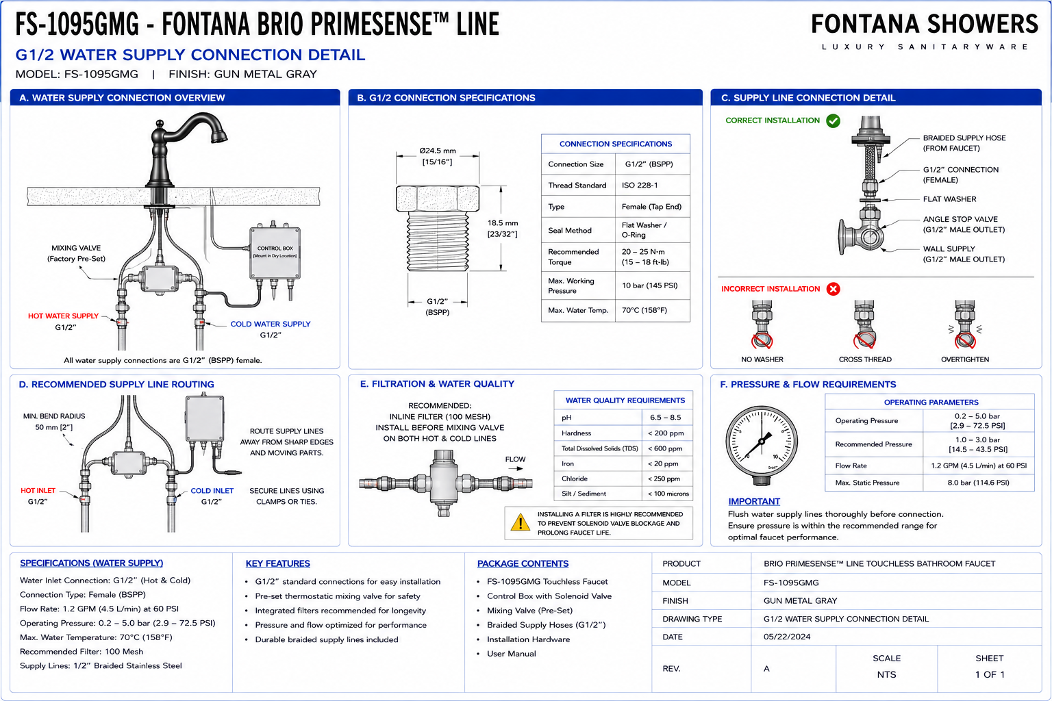
The water-supply connection drawing should show the complete hydraulic path
from the project hot- and cold-water stub-outs to the faucet inlet. The
drawing should identify the G1/2 angle stops, braided hoses, mixing valve,
solenoid valve, mixed-water connection, faucet inlet, water-flow direction,
accessible isolation points and required separation from drainage and
electrical components. Final connections should remain visible and
serviceable after cabinet completion.
Complete G1/2 Water Supply Connection Detail
Shows the complete hydraulic sequence from the building hot- and
cold-water supplies through G1/2 isolation valves, braided hoses,
mixing valve, solenoid valve and final faucet connection.
Hot-Water Supply Stub-Out
Identify the project hot-water supply terminating within the
under-counter cabinet. The stub-out location should permit a direct
connection to an accessible G1/2 isolation valve without interfering
with the basin, trap or cabinet structure.
Cold-Water Supply Stub-Out
Show the cold-water supply point below the lavatory. Coordinate the
stub-out location with the hot-water connection so both angle stops
remain visible, accessible and clearly identifiable.
G1/2 Hot-Water Angle Stop
Provide an accessible G1/2 hot-water isolation valve serving the
faucet system. The valve should remain reachable for commissioning,
leak testing and future maintenance.
G1/2 Cold-Water Angle Stop
Provide an accessible G1/2 cold-water shutoff valve. The connection
should be positioned to permit flexible-hose installation without
kinking or excessive bending.
Hot-Water Braided Hose
Show the flexible braided connection between the hot-water angle stop
and the designated hot inlet of the mixing valve. Maintain a smooth
bend radius and avoid twisting the hose during tightening.
Cold-Water Braided Hose
Show the braided cold-water hose between the cold-water angle stop
and mixing-valve inlet. The hose should not be stretched, compressed
against the basin or routed around sharp cabinet edges.
Hot and Cold Identification
Clearly identify the hot and cold hydraulic paths on the installation
drawing. Red and blue line conventions may be used to assist field
coordination and reduce connection errors.
Mixing Valve Hot Inlet
Show the hot-water hose connecting to the correct mixing-valve inlet.
Confirm inlet identification before pressurizing the system.
Mixing Valve Cold Inlet
Identify the designated cold-water inlet on the mixing assembly.
Reversed connections can adversely affect delivered water
temperature and commissioning.
Under-Counter Mixing Valve
The mixing valve combines the hot- and cold-water supplies before
water enters the electronically controlled valve. Mount or support
the valve so it does not hang solely from flexible hoses.
Mixed-Water Outlet
Identify the mixed-water outlet leaving the mixing valve and feeding
the automatic valve assembly. The connection should remain accessible
for inspection and service.
Solenoid Valve Inlet
Show the mixed-water supply entering the solenoid valve at the
designated inlet. Confirm valve orientation and any molded or marked
flow-direction indicators before installation.
Solenoid Valve Outlet
Show the solenoid outlet connected toward the faucet inlet. The
automatic valve should be positioned so both hydraulic connections
and electrical connectors remain accessible.
Water-Flow Direction
Use arrows to show flow from the building supplies through the
isolation valves, mixing assembly, solenoid valve and faucet.
Incorrect flow orientation can impair automatic valve operation.
Solenoid-to-Faucet Hose
Show the final flexible connection carrying controlled mixed water
from the solenoid valve to the faucet inlet. Maintain a smooth,
unrestricted route.
Faucet Water Inlet
Identify the final hydraulic connection entering the deck-mounted
faucet assembly. The connection should remain free from twisting and
should not transfer hose load to the faucet mounting stem.
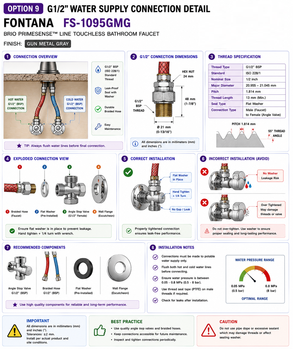
Threaded Connection Engagement
Show full and proper engagement of G1/2 threaded connections.
Connections should be assembled using the sealing method specified
for the supplied fitting type without damaging threads.
Connection Sealing
Apply the approved sealing method only where required by the fitting
design. Do not apply unnecessary sealant to compression, gasketed or
factory-sealed connections.
Braided Hose Bend Radius
Provide smooth curves in all flexible supply hoses. Tight bends
immediately adjacent to fittings should be avoided to reduce stress
and maintain unrestricted flow.
Hose Tension Control
Hoses should not be stretched between connection points. Provide
enough length to allow natural movement and future component
servicing.
Hose Twist Prevention
Hold the hose in alignment while tightening fittings so the braided
connection does not rotate or become torsion-loaded.
Drain Separation
Keep the water-supply hoses and automatic valve assembly clear of the
lavatory drain and trap so each system can be serviced independently.
Electrical Separation
Do not route water connections directly above the electronic control
box or exposed electrical connectors where leakage could damage
components.
Isolation Access Zone
Reserve clear access to the hot- and cold-water angle stops so a
technician can isolate the faucet without removing the control box,
trap or cabinet components.
Connection Inspection Zone
Keep hose connections and valve fittings visible after installation
so slow leaks or moisture accumulation can be identified during
maintenance.
Pressure Test Connection Area
The complete hydraulic path should be pressure tested before cabinet
access is restricted. Inspect every threaded and flexible connection
under normal system pressure.
Finished Hydraulic Arrangement
The final connection layout should present an orderly and clearly
identified hot-, cold- and mixed-water path with accessible shutoff
valves and serviceable automatic controls.
Engineering note:
Confirm the actual thread configuration and supplied fittings before final
connection. The G1/2 water-supply designation should be coordinated with
project plumbing components and approved manufacturer documentation.
Do not force incompatible NPT, BSP or other threaded systems together.
Required Water Supply Connection Drawing Views
Front Connection Elevation
Show hot and cold stub-outs, G1/2 angle stops, braided hoses,
mixing valve, solenoid valve and faucet connection.
Side Cabinet Section
Show supply-valve depth, basin clearance, hose-routing path and
relationship to the drain and control box.
Hydraulic Flow Diagram
Show the sequence: hot supply and cold supply to mixing valve,
mixing valve to solenoid valve, and solenoid valve to faucet.
G1/2 Connection Enlargement
Provide an enlarged fitting detail identifying the G1/2 connection,
hose fitting, sealing interface and required wrench-access zone.
Under-Counter Plan View
Show the basin footprint, supply valves, mixing valve, solenoid
valve, trap and hydraulic connection routes.
Service-Access Diagram
Show clear access to angle stops, hose fittings, valve assemblies
and connection points required for future servicing.
Recommended G1/2 Water Connection Sequence
1. Verify Supply Type
Confirm the project hot- and cold-water supplies and compatible
G1/2 connection arrangement before installing faucet components.
2. Flush Supply Piping
Flush the building water lines thoroughly before connecting the
mixing and solenoid valves to remove construction debris.
3. Install Angle Stops
Install accessible hot- and cold-water shutoff valves and verify
that each valve operates correctly.
4. Connect Hot Supply Hose
Connect the hot-water braided hose from the angle stop to the
correct mixing-valve inlet.
5. Connect Cold Supply Hose
Connect the cold-water hose from the isolation valve to the
corresponding mixing-valve inlet.
6. Connect Mixed-Water Outlet
Route the mixed-water connection from the mixing valve to the
solenoid-valve inlet.
7. Verify Solenoid Orientation
Check the automatic valve inlet, outlet and flow-direction marking
before final tightening.
8. Connect Faucet Supply
Connect the solenoid-valve outlet to the faucet inlet using the
approved flexible connection.
9. Open Supplies Slowly
Open the isolation valves gradually and allow the hydraulic system
to pressurize while observing all connections.
10. Inspect for Leaks
Check each angle stop, hose fitting, mixing valve, solenoid valve
and faucet connection for leakage.
11. Verify Water Temperature
Operate the faucet and confirm the mixed-water temperature is
appropriate for the project application.
12. Complete Final Commissioning
Verify stable flow, proper automatic shut-off and leak-free
operation before closing or restricting cabinet access.
G1/2 Connection & Thread Coordination
Connection Standard
The drawing should identify G1/2 connections clearly so compatible
project fittings and shutoff valves are selected.
Thread Compatibility
Verify thread type before assembly. Do not assume G1/2 and 1/2-inch
NPT are directly interchangeable without an approved adapter.
Adapter Coordination
Where project piping uses another connection standard, provide an
approved transition fitting without placing excessive mechanical
load on the faucet hoses.
Gasketed Connections
Where a flat gasket or washer provides the seal, verify it is clean,
undamaged and correctly seated before tightening.
Threaded Connections
Where tapered or threaded sealing is specified, use only the
appropriate approved thread-sealing method.
Wrench Clearance
Provide enough space around supply and valve fittings to permit
proper tightening without damaging nearby components.
Hydraulic Routing & Clearance Considerations
Basin Clearance
Keep braided hoses and valve bodies clear of the underside of the
basin to prevent abrasion and compression.
Trap Clearance
The drain trap should remain independently removable without
disconnecting faucet water-supply components.
Cabinet Rail Clearance
Structural rails should not force water hoses into tight turns or
block access to G1/2 connection points.
Drawer Clearance
Verify moving drawers cannot contact angle stops, hoses or the
mixing and solenoid valve assemblies.
Controller Clearance
Keep water connections away from the electronic controller and
electrical connectors wherever practical.
Service Clearance
Preserve a clear working area allowing hose replacement, valve
isolation and fitting inspection without removing the basin.
Leak Testing & Commissioning
Visual Inspection
Inspect each threaded and flexible connection before opening the
water supply.
Slow Pressurization
Open isolation valves gradually so installation personnel can
observe the system as pressure increases.
Static Leak Test
With the faucet inactive, inspect the pressurized hydraulic system
for seepage at all supply and valve connections.
Dynamic Leak Test
Operate the faucet repeatedly and inspect connections while water is
flowing through the mixing and solenoid assemblies.
Flow Verification
Confirm stable flow through the faucet and investigate restricted
hoses or partially closed valves if performance is abnormal.
Final Dry Inspection
Dry all connections after testing and perform a final visual check
for slow moisture accumulation before project turnover.
G1/2 Water Supply Connection Notes
-
Verify connection standard:
Confirm the exact G1/2 thread configuration and fitting compatibility
before installation.
-
Flush water lines:
Remove construction debris before connecting the mixing and solenoid
valve assembly.
-
Accessible isolation:
Provide separate accessible hot- and cold-water shutoff valves.
-
Correct hot and cold orientation:
Connect each supply to the corresponding mixing-valve inlet.
-
Observe flow direction:
Install the solenoid valve in the intended hydraulic direction.
-
Avoid hose kinks:
Route braided connections using smooth curves and adequate bend radius.
-
Avoid hose tension:
Do not stretch flexible hoses between fixed connection points.
-
Keep electronics dry:
Do not locate hydraulic fittings directly above exposed electrical
components where practical.
-
Leak test:
Inspect all connections under static and operating pressure.
-
Maintain service access:
All G1/2 connections and isolation valves should remain accessible after
cabinet completion.
Water Supply Component Identification
-
Hot-water supply:
Building water line supplying hot water to the faucet system.
-
Cold-water supply:
Building water line supplying cold water.
-
G1/2 hot angle stop:
Accessible isolation valve serving the hot-water branch.
-
G1/2 cold angle stop:
Accessible isolation valve serving the cold-water branch.
-
Hot-water braided hose:
Flexible connection between the hot angle stop and mixing valve.
-
Cold-water braided hose:
Flexible connection between the cold angle stop and mixing valve.
-
Mixing valve:
Combines hot and cold water before automatic flow control.
-
Mixed-water outlet:
Connection carrying tempered water from the mixing valve.
-
Solenoid valve:
Electronically opens and closes the faucet water supply.
-
Solenoid inlet:
Mixed-water connection entering the automatic valve.
-
Solenoid outlet:
Controlled water connection leaving the automatic valve.
-
Faucet supply hose:
Final flexible connection between the automatic valve and faucet.
-
Faucet inlet:
Hydraulic connection delivering controlled water into the fixture.
-
Flow-direction arrow:
Graphic indicator showing the intended direction of water movement.
-
Service-access zone:
Clear working area around shutoff valves, hoses and automatic controls.
FontanaShowers Installation and Specification Resources
Professional Engineering and Plumbing References
Project verification:
This G1/2 water-supply connection detail is intended for architectural,
plumbing and installation coordination and does not replace approved
manufacturer instructions or project submittals. The architect, plumbing
engineer, mechanical contractor and licensed installer should verify the
project water-supply connection standard, G1/2 thread compatibility, hot- and
cold-water isolation valves, braided hoses, mixing-valve connections, solenoid
valve flow direction, faucet inlet, hose routing, operating pressure, sealing
method, leak-testing procedure, service accessibility and locally adopted
plumbing-code requirements before final installation.
|
|
|