Fontana Touchless Faucets™ | Architectural and Engineering Resource
Fontana Brio PrimeSense™ Line FS-1095GMG Gun Metal Gray Touchless Bathroom Faucet:
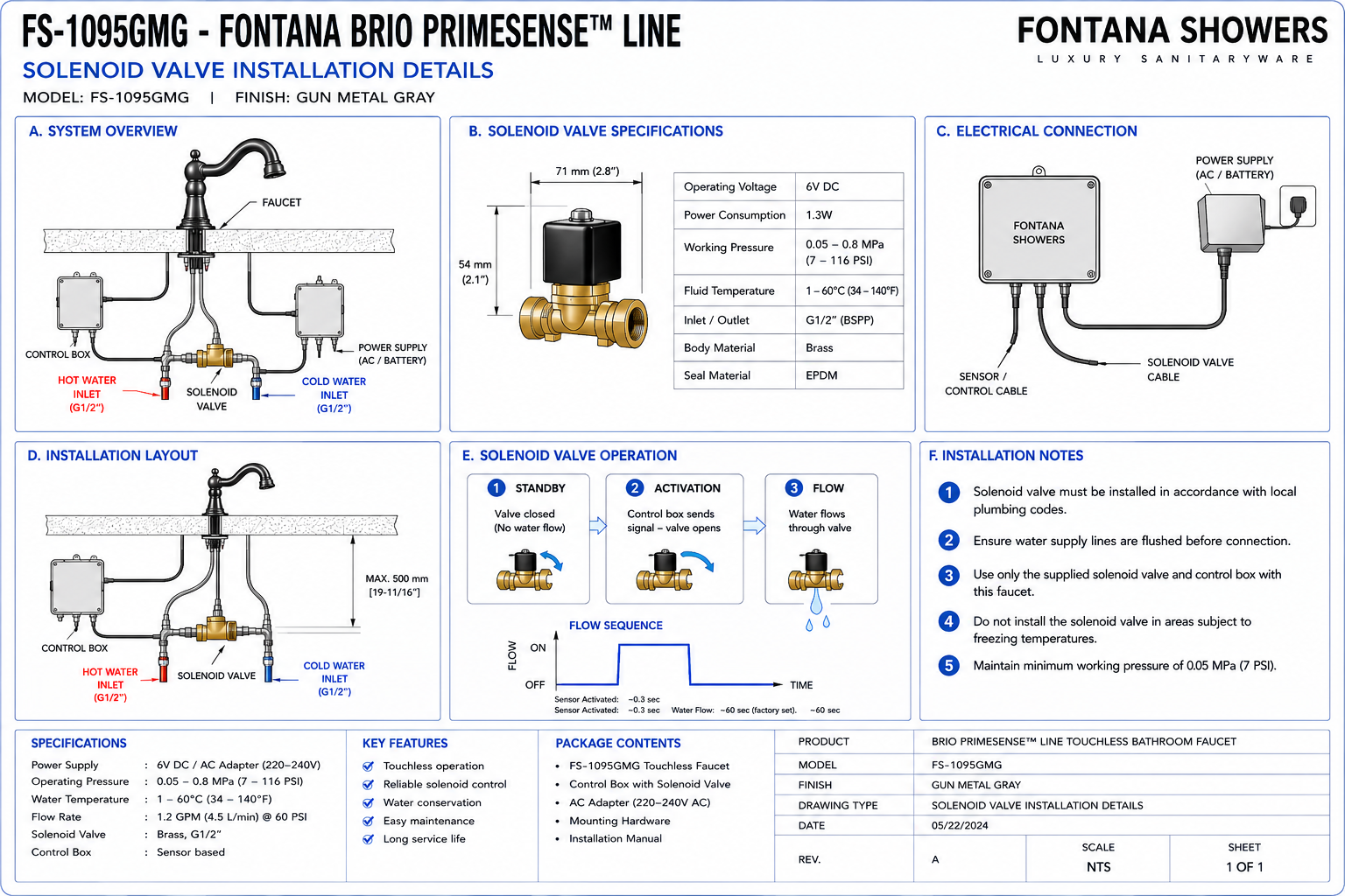
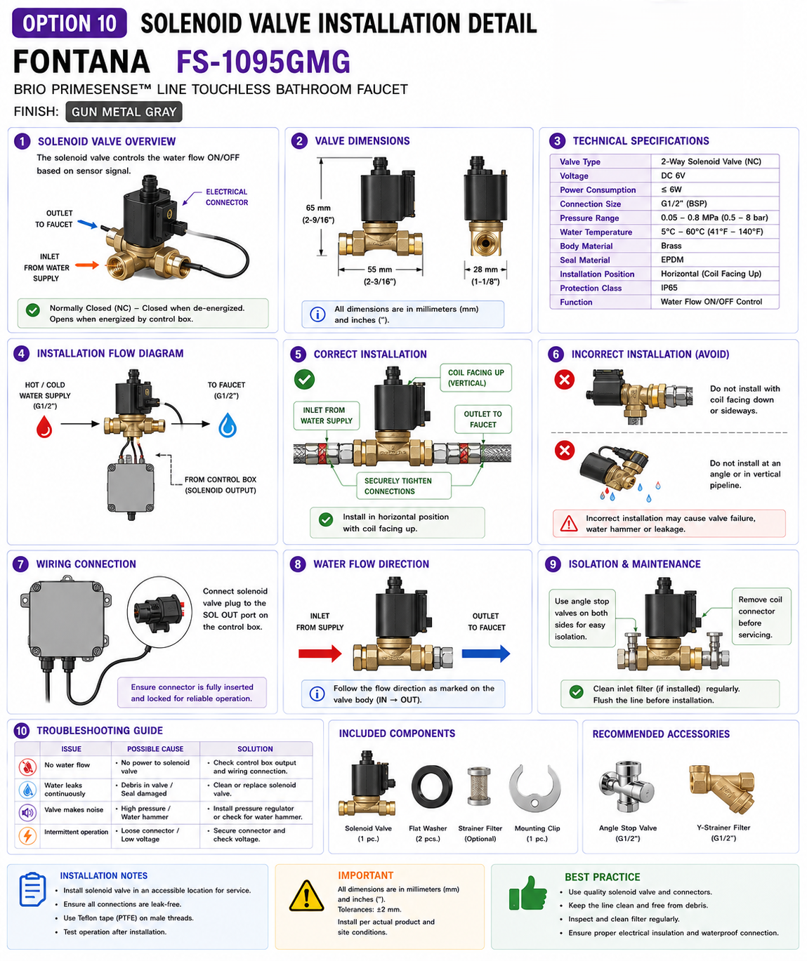
Solenoid Valve Installation Detail
This solenoid-valve installation-detail resource is intended to support
architects, plumbing engineers, electrical engineers, contractors, installers,
commissioning technicians and facility managers coordinating the concealed
automatic water-control assembly for the Fontana Brio PrimeSense™ Line
FS-1095GMG touchless bathroom faucet. The detail identifies the solenoid valve
body, mixed-water inlet, controlled outlet, directional-flow orientation,
electrical connector, controller cable, mounting position, adjacent mixing valve,
flexible hose connections, G1/2 water connections, drainage separation and
maintenance-access requirements below the countertop.
Fontana Brio PrimeSense™ Line FS-1095GMG Touchless Bathroom Faucet
The Fontana FS-1095GMG uses an electronically controlled solenoid valve
to start and stop water flow in response to the faucet's infrared sensor.
The valve is installed below the countertop within the hydraulic path
between the mixed-water supply and faucet inlet. Correct flow direction,
stable mounting, accessible hose connections and protected electrical
wiring are essential for reliable automatic operation.
-
Model:
FS-1095GMG
-
Product type:
Touchless bathroom faucet
-
Installation:
Single-hole deck mount
-
Finish:
Gun Metal Gray
-
Automatic water control:
Electronic solenoid valve
-
Water connection:
G1/2"
-
Upstream component:
Under-counter mixing valve
-
Downstream connection:
Faucet supply hose
-
Electronic control:
Touchless sensor controller
-
Flow rate:
1.2 GPM [4.5 L/min] at 60 PSI
-
Operating pressure:
0.2–5.0 bar [2.9–72.5 PSI]
-
Service requirement:
Accessible under-counter installation
-
Application:
Commercial and institutional washrooms
Required Solenoid Valve Installation Drawing Package
The solenoid-valve drawing should show the automatic valve as part of the
complete under-counter hydraulic and electrical system. The drawing should
identify the mixed-water inlet, valve body, directional-flow arrow, controlled
outlet, flexible hose connections, controller cable, electrical connector,
adjacent mixing valve, faucet supply connection, control box and service
clearance. The valve should be positioned where all hydraulic and electrical
connections can be inspected and serviced without removing the countertop.
Complete Solenoid Valve Installation Detail
Shows the complete automatic valve assembly between the under-counter
mixing valve and faucet inlet. The detail identifies the hydraulic
inlet and outlet, flow direction, valve body, electrical connection,
controller wiring and maintenance-access area.
Solenoid Valve Body
Identify the complete valve assembly responsible for automatically
opening and closing the mixed-water supply. The valve body should be
mounted in a stable and accessible location beneath the countertop.
Mixed-Water Inlet
Show the connection receiving tempered water from the under-counter
mixing valve. The inlet should be clearly differentiated from the
outlet before installation and commissioning.
Controlled Water Outlet
Identify the solenoid outlet supplying the faucet. The connection
should lead directly toward the faucet inlet without unnecessary hose
loops or restrictive bends.
Flow-Direction Arrow
Show the manufacturer's intended direction of water flow through the
valve body. The installer should verify the molded, engraved or
printed direction indicator before connecting the valve.
Correct Valve Orientation
Install the solenoid in the approved hydraulic orientation. Reversed
inlet and outlet connections can prevent proper operation or cause
unstable automatic shut-off performance.
G1/2 Inlet Connection
Show the G1/2 hydraulic connection entering the valve assembly.
Verify the actual supplied fitting and thread type before connecting
project plumbing.
G1/2 Outlet Connection
Identify the G1/2 connection on the downstream side where applicable.
Maintain sufficient clearance for proper connection tightening and
future disassembly.
Upstream Mixing Valve
Show the mixing valve upstream of the solenoid. Hot and cold water
should be mixed before entering the automatic valve unless the
approved product configuration specifies otherwise.
Mixing-Valve-to-Solenoid Hose
Provide a smooth flexible connection between the mixed-water outlet
and solenoid inlet. Avoid twisting, stretching or sharply bending the
hose.
Solenoid-to-Faucet Hose
Show the downstream hose carrying automatically controlled water from
the valve to the faucet inlet. The connection should remain free from
kinks and mechanical loading.
Electromagnetic Coil
Identify the electrical actuator attached to the hydraulic valve
body. The coil receives the controller signal and operates the valve
in response to sensor activation.
Solenoid Electrical Connector
Show the electrical connector between the solenoid actuator and
control wiring. The connector should remain dry, fully seated and
accessible for diagnostic testing.
Controller-to-Solenoid Cable
Route the control cable from the electronic control box to the valve
without sharp bends, tension or exposure to moving cabinet hardware.
Control Box Relationship
Show the valve in relation to the electronic controller. The control
box and solenoid should remain within the approved cable reach while
maintaining separation from potential leak points.
Sensor Control Relationship
The infrared sensor sends a signal to the controller, which energizes
the solenoid to open the water path. The valve closes when the
controller no longer receives an active detection signal.
Valve Mounting Position
Position the valve where it is supported and not suspended only by
flexible water hoses. Use the approved support method where mounting
provisions are provided.
Valve Support Surface
Where the assembly is secured to a cabinet wall or support panel,
ensure the mounting surface is stable and allows the valve to be
removed without dismantling permanent millwork.
Vertical Clearance
Provide sufficient space above and below the valve to disconnect
hydraulic fittings and remove the electrical actuator if service is
required.
Lateral Clearance
Maintain adequate side clearance for hose fittings, connector access
and wrench movement without interference from the basin or cabinet
framing.
Service Access Zone
Reserve an unobstructed working area around the valve so a technician
can isolate water, disconnect hoses, inspect wiring and remove the
valve assembly.
Drain Separation
Keep the solenoid valve clear of the lavatory drain and trap.
Drainage fittings should remain independently removable without
disturbing the automatic faucet system.
Electrical Moisture Protection
Position the electrical connector away from supply joints, trap
connections and locations where water may drip or accumulate.
Cabinet Floor Clearance
Keep the valve's electrical connections and controller components
above the cabinet floor where practical to reduce exposure to
cleaning water and minor leaks.
Inlet Strainer or Debris Protection
Where the supplied valve assembly includes a strainer or filter,
identify its location and maintain sufficient access for cleaning
during commissioning and maintenance.
Thread and Seal Interface
Show the sealing method appropriate to the supplied fitting.
Do not apply thread sealant to gasketed or factory-sealed connections
unless specifically required.
Leak Inspection Zone
Keep the valve and adjacent hose fittings visible after installation
so slow leakage can be detected during commissioning and routine
maintenance.
Finished Solenoid Installation
The final arrangement should present a supported, correctly oriented
valve with clear water-flow direction, accessible hydraulic
connections, protected wiring and an unobstructed removal path.
Engineering note:
Do not install the solenoid valve solely by visual similarity between its
connections. Verify the designated inlet, outlet, flow-direction marking,
thread type, supplied seals, controller connector and approved mounting
orientation before pressurizing the faucet system.
Required Solenoid Valve Drawing Views
Front Installation Elevation
Show the solenoid valve, mixing valve, inlet hose, outlet hose,
controller cable and surrounding service-clearance zone.
Side Installation Section
Show valve depth, basin clearance, hose routing and electrical
connector accessibility.
Hydraulic Flow Diagram
Show the sequence from mixing valve to solenoid inlet, through the
valve and onward to the faucet.
Electrical Control Diagram
Show the faucet sensor, electronic controller, controller-to-solenoid
cable and valve actuator.
Valve Connection Enlargement
Provide an enlarged view of the inlet, outlet, seals, thread
engagement and directional-flow marking.
Service Removal Diagram
Show the direction in which the valve can be disconnected and removed
without interfering with the basin, drain or permanent cabinet.
Recommended Solenoid Valve Installation Sequence
1. Flush the Water Supply
Flush the hot- and cold-water lines before connecting the automatic
valve system so construction debris does not enter the solenoid.
2. Verify Mixing Valve Installation
Confirm the upstream mixing assembly is correctly connected and
supported before installing the solenoid valve.
3. Identify Solenoid Inlet
Locate the designated inlet connection and verify the valve's
flow-direction marking.
4. Identify Solenoid Outlet
Confirm the downstream outlet connection before attaching the
faucet supply hose.
5. Position the Valve
Locate the valve in a dry, accessible area with adequate clearance
from the basin, trap and cabinet hardware.
6. Support the Valve
Secure the valve where required so flexible hoses do not carry the
full component weight.
7. Connect Mixed-Water Inlet
Connect the mixing-valve outlet to the solenoid inlet using the
approved hose or fitting.
8. Connect Faucet Outlet Hose
Connect the valve outlet to the faucet supply while maintaining a
smooth hose route.
9. Connect Electrical Cable
Connect the solenoid actuator to the designated control-box output
and verify the connector is fully seated.
10. Inspect Hose Routing
Confirm neither inlet nor outlet hose is kinked, twisted or under
tension.
11. Pressurize and Leak Test
Open the water supplies slowly and inspect the solenoid inlet,
outlet and adjacent hydraulic connections for leakage.
12. Perform Functional Test
Activate the faucet repeatedly and verify the valve opens and closes
consistently in response to the sensor.
Hydraulic Solenoid Valve Coordination
Upstream Water Quality
Flush debris from supply piping before commissioning because foreign
material can impair the small internal passages of automatic valves.
Operating Pressure
Verify building pressure remains within the approved faucet operating
range before testing the solenoid valve.
Mixed-Water Supply
The valve should receive water from the approved temperature-mixing
arrangement so its hydraulic path is consistent with the faucet
system design.
Hose Bend Radius
Provide smooth hose curves on both sides of the valve to reduce
connection stress and preserve full flow.
Connection Stress
Do not use the valve body as a lever when tightening hose or threaded
fittings.
Hydraulic Isolation
Maintain accessible upstream shutoff valves so the solenoid can be
serviced without shutting down unrelated fixtures.
Electrical Solenoid Valve Coordination
Control Cable
Route the controller cable in a protected path and keep it clear of
sharp edges, drawer slides and moving cabinet components.
Connector Orientation
Fully seat the electrical connector without forcing incompatible
plug orientation or damaging connector pins.
Moisture Protection
Keep all valve electrical connections away from possible spray,
drips and water accumulation.
Strain Relief
Support the cable so the electrical connector does not carry the
weight of hanging wiring.
Controller Compatibility
Use the valve with the approved Fontana control system and designated
controller connection supplied for the faucet.
Diagnostic Access
Keep the connector visible and accessible so electrical continuity
and controller output can be checked during troubleshooting.
Solenoid Valve Commissioning Tests
Static Leak Test
Pressurize the valve while the faucet is inactive and inspect the
inlet and outlet for leakage.
Activation Test
Place hands in the sensing zone and verify the solenoid opens
promptly.
Deactivation Test
Remove hands from the sensor field and verify the valve closes and
water flow stops consistently.
Repeated-Cycle Test
Run multiple activation cycles to verify consistent opening and
closing without sticking or intermittent response.
Flow Test
Confirm the valve provides unrestricted flow when open and does not
create abnormal noise or vibration.
Final Dry Inspection
Dry the valve and fittings after testing and inspect again for slow
seepage before project turnover.
Solenoid Valve Troubleshooting Considerations
Valve Does Not Open
Check controller power, sensor activation, cable connection, supply
isolation valves and possible inlet blockage before replacing the
valve.
Valve Does Not Close
Check for continuous sensor activation, debris in the valve,
controller output or incorrect valve installation.
Low Flow
Check for supply restrictions, kinked hoses, partially closed angle
stops, debris or incorrect flow orientation.
Intermittent Operation
Inspect electrical connectors, controller wiring and sensor
calibration before assuming a hydraulic valve failure.
Valve Noise
Verify the valve is supported, supply pressure is appropriate and
hydraulic connections are not transmitting vibration into the
cabinet.
Slow Leakage
Inspect hose seals and valve connections and determine whether the
leak originates from a fitting or the valve body itself.
Solenoid Valve Installation Notes
-
Verify flow direction:
Install the valve according to the marked inlet-to-outlet direction.
-
Flush supply piping:
Remove debris before connecting the automatic valve assembly.
-
Support the valve:
Do not allow the component to hang unsupported from flexible hoses.
-
Maintain hose bend radius:
Use smooth curves and avoid sharp bends immediately adjacent to fittings.
-
Protect electrical connections:
Keep the valve connector dry and clear of plumbing leak points.
-
Do not overtighten:
Use appropriate connection techniques and avoid excessive force on the
valve body.
-
Maintain service access:
The valve should be removable without removing the countertop or basin.
-
Leak test:
Inspect inlet and outlet connections under normal static and operating
pressure.
-
Functional test:
Verify repeated opening and closing in response to sensor activation.
-
Record commissioning:
Document any valve, sensor or controller adjustments made during project
startup.
Solenoid Valve Component Identification
-
Solenoid valve body:
Hydraulic component controlling automatic faucet flow.
-
Mixed-water inlet:
Connection receiving water from the mixing valve.
-
Controlled outlet:
Connection delivering water toward the faucet.
-
Flow-direction indicator:
Arrow or marking identifying required hydraulic orientation.
-
Electromagnetic coil:
Electrical actuator that opens or closes the hydraulic valve.
-
Electrical connector:
Interface between the solenoid coil and controller cable.
-
Controller cable:
Transfers control signals from the electronic control box to the valve.
-
Inlet hose:
Flexible connection carrying mixed water to the valve.
-
Outlet hose:
Flexible connection carrying controlled water to the faucet.
-
Mixing valve:
Upstream component providing the mixed-water supply.
-
Electronic controller:
Processes infrared sensor input and commands solenoid operation.
-
Valve support:
Mounting provision preventing unsupported loading on hydraulic hoses.
-
Service zone:
Clear working area around the valve for inspection and replacement.
FontanaShowers Installation and Specification Resources
Professional Engineering and Plumbing References
Project verification:
This solenoid-valve installation detail is intended for plumbing, electrical,
millwork, commissioning and maintenance coordination and does not replace
approved manufacturer instructions or project submittals. The plumbing engineer,
electrical engineer, licensed installer and commissioning technician should
verify the valve inlet, outlet, flow direction, G1/2 connection compatibility,
mixed-water supply, hose routing, valve support, electrical connector,
controller wiring, operating pressure, service clearances, leakage protection
and functional operating sequence before final project turnover.
|
|
|