Fontana Touchless Faucets™ | Architectural and Engineering Resource
Fontana Brio PrimeSense™ Line FS-1095GMG Gun Metal Gray Touchless Bathroom Faucet:
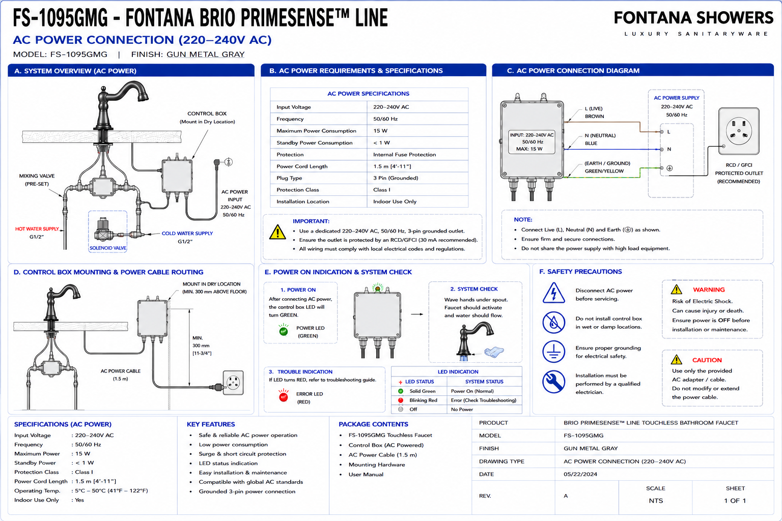
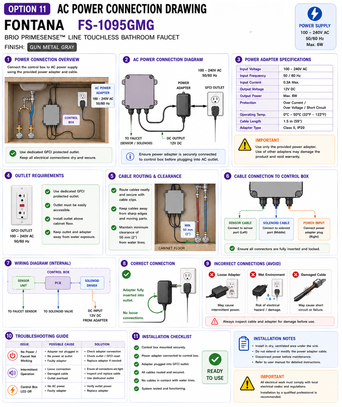
AC Power Connection Drawing
This AC power-connection drawing resource is intended to support architects,
electrical engineers, plumbing engineers, MEP coordinators, contractors,
installers, commissioning technicians and facility managers coordinating the
Fontana Brio PrimeSense™ Line FS-1095GMG touchless bathroom faucet. The drawing
identifies the 220–240V AC power source, transformer or approved power adapter,
controller input, low-voltage control wiring, solenoid-valve connection,
sensor cable, cable-routing path, receptacle or junction location, waterproof
cable penetration, plumbing separation and required service-access area beneath
the finished countertop.
Fontana Brio PrimeSense™ Line FS-1095GMG Touchless Bathroom Faucet
The Fontana FS-1095GMG uses an electronic control system to process
infrared sensor input and operate the automatic water-control valve.
For AC installations, the faucet supports a 220–240V AC, 50/60Hz power
supply arrangement. The incoming electrical source should connect
through the approved power component to the faucet controller while
low-voltage sensor and solenoid wiring remains organized, protected
and separated from plumbing connections.
-
Model:
FS-1095GMG
-
Product type:
Touchless bathroom faucet
-
Installation:
Single-hole deck mount
-
Finish:
Gun Metal Gray
-
Primary AC supply:
220–240V AC
-
Frequency:
50/60Hz
-
Alternative power:
DC 6V using 4 × AA batteries
-
Electronic control:
Touchless control module
-
Sensor opening time:
Less than 1 second
-
Sensor closing time:
Less than 2 seconds
-
Automatic safety shut-off:
30 seconds
-
Water connection:
G1/2" inlet and outlet
-
Flow rate:
1.2 GPM [4.54 L/min] at 60 PSI
-
Application:
Commercial and institutional washrooms
Required AC Power Connection Drawing Package
The AC power drawing should document the electrical path from the project
220–240V AC source to the approved faucet power component and electronic
controller. The drawing should identify the receptacle or junction location,
AC adapter or transformer, control box, low-voltage sensor cable,
solenoid-valve cable, cable connectors, waterproof penetrations and required
separation from water-supply and drainage components. Final wiring should
remain accessible for commissioning and maintenance.
Complete AC Power Connection Drawing
Shows the complete electrical path from the 220–240V AC project
supply through the approved power adapter or transformer to the
electronic controller, sensor and solenoid valve.
220–240V AC Supply
Identify the project electrical source serving the touchless faucet.
The drawing should clearly note the 220–240V AC, 50/60Hz operating
requirement of the AC configuration.
50/60Hz Frequency
Include the required 50/60Hz supply frequency within the electrical
connection notes so the project electrical system can be verified
before commissioning.
Power Receptacle Location
Where a receptacle is used, locate it inside the cabinet in a dry,
accessible position that does not interfere with the basin, drain,
angle stops or service access.
Junction or Connection Point
Where the approved system uses a fixed electrical connection,
identify the junction location and coordinate it with project
electrical requirements and local codes.
Approved AC Power Adapter
Show the approved adapter or power-conversion component between the
building AC source and electronic controller. The component should
not rest loose on the cabinet floor.
Transformer Location
Where a transformer is supplied as part of the installation
configuration, mount it in a dry, ventilated and serviceable position
away from plumbing leak points.
Controller Power Input
Identify the designated power-input connection on the electronic
control box. Only the approved power component should be connected
to this input.
Electronic Control Box
Mount the controller securely on a vertical cabinet wall or approved
support surface where practical. The enclosure should remain
accessible for inspection and diagnostic testing.
Controller Mounting Height
Position the control box above the lowest cabinet level where
practical to reduce the risk of exposure to cleaning water,
condensation or minor plumbing leaks.
Sensor Cable Connection
Show the low-voltage cable from the faucet's infrared sensor to the
controller. The connector should be fully seated and remain accessible
for commissioning and troubleshooting.
Solenoid Control Cable
Identify the electrical connection between the controller and
motorized solenoid valve. Route this cable independently from
water-supply hoses where practical.
Low-Voltage Wiring Zone
Create an organized routing zone for sensor and valve-control wiring
so these cables are separated from sharp edges, drawer slides,
hinges and plumbing components.
AC and Low-Voltage Separation
Where project conditions require separate wiring routes, show the
physical separation between incoming AC wiring and faucet
low-voltage control cables.
Power Cable Route
Route the power cable directly to the control system without
excessive loops, sharp bends or compression against cabinet
structure.
Cable Strain Relief
Provide sufficient support so cable weight or movement is not
transferred directly to controller plugs, adapter connectors or
solenoid terminals.
Waterproof Cable Grommet
Show a protected grommet or equivalent treatment wherever wiring
passes through a cabinet panel or other enclosure surface.
Cabinet Penetration
Cable penetrations should be smooth and protected from sharp edges.
Where moisture exposure is possible, coordinate the penetration with
an appropriate sealing method.
Water-Supply Separation
Keep AC adapters, electrical connectors and the control box separated
from hot- and cold-water angle stops, braided hoses and valve joints.
Drain Separation
Do not locate the power adapter or controller directly beneath the
lavatory trap, tailpiece or other drainage connections that may leak
during service.
Drip-Risk Exclusion Zone
Establish a dry electrical zone that avoids areas directly below
supply fittings, hose unions, mixing valves and drain joints.
Cabinet Floor Clearance
Do not place the AC power adapter, transformer or loose electrical
connectors directly on the cabinet floor where water may collect.
Service Disconnect Access
Provide a serviceable means of disconnecting faucet power without
removing the basin, countertop or permanent cabinet construction.
Connector Identification
Label or clearly differentiate the power, sensor and solenoid
connectors so field technicians can identify each connection during
commissioning.
Cable Service Loop
Where appropriate, provide a modest service loop sufficient to allow
the controller to be inspected without placing tension on cable
connectors.
Controller Access Zone
Maintain clear working space in front of the control box so power,
sensor and valve connections can be reached during maintenance.
Power Component Removal Path
Show how the transformer or AC adapter can be removed from the cabinet
without disconnecting the basin or dismantling permanent millwork.
Finished AC Electrical Arrangement
The completed installation should present an organized electrical
system with securely mounted components, protected cables, clearly
identified connectors and appropriate separation from plumbing.
Engineering note:
The product page identifies a 220–240V AC, 50/60Hz operating option and an
alternative DC 6V battery configuration. The exact adapter, transformer,
receptacle, wiring method and branch-circuit requirements should be verified
against the approved FontanaShowers installation instructions and applicable
project electrical requirements before final connection.
Required AC Power Drawing Views
Front Cabinet Elevation
Show the AC source, power adapter, controller, solenoid valve,
sensor wiring and relationship to plumbing components.
Side Cabinet Section
Show the controller mounting plane, receptacle depth, basin envelope,
drain separation and required electrical service space.
Electrical Connection Diagram
Show the 220–240V AC source, approved adapter or transformer,
controller, sensor and solenoid valve connections.
Low-Voltage Control Diagram
Show the signal path from the infrared sensor to the controller and
from the controller to the motorized valve.
Cable Routing Detail
Show supported wiring routes, service loops, waterproof grommets and
separation from plumbing and moving cabinet hardware.
Service Access Detail
Show the clear working area required to disconnect power, inspect
connectors and remove the controller or adapter.
Recommended AC Power Installation Sequence
1. Verify Power Configuration
Confirm the project will use the 220–240V AC configuration rather
than the alternative DC battery arrangement.
2. Review Approved Submittal
Verify the exact transformer, adapter, controller and connector
arrangement before installing electrical infrastructure.
3. Coordinate Power Location
Establish the receptacle or approved electrical connection point in a
dry, accessible portion of the cabinet.
4. Mount the Controller
Fasten the electronic control box to a stable cabinet surface above
areas where water is likely to accumulate.
5. Mount Power Components
Secure the approved transformer or adapter so it does not hang from
its electrical cable or rest on the cabinet floor.
6. Route AC Power
Route incoming electrical wiring in accordance with the approved
project electrical design and applicable requirements.
7. Connect Controller Power
Connect the approved power output to the designated controller input
without forcing or modifying the supplied connector.
8. Connect Sensor Cable
Route and connect the faucet sensor cable to the corresponding
controller input.
9. Connect Solenoid Cable
Connect the motorized valve to the designated controller output and
secure excess cable away from plumbing.
10. Inspect Cable Routing
Confirm all wiring is protected from sharp edges, water exposure,
drawer slides and hinge movement.
11. Energize the System
After hydraulic connections have been inspected, energize the faucet
and confirm the controller powers correctly.
12. Perform Functional Commissioning
Test sensor response, solenoid opening and closing, automatic
shut-off and overall faucet operation before project turnover.
AC Power & Controller Coordination
Input Voltage
The current product specification identifies 220–240V AC operation
for the AC-powered configuration.
Frequency
The AC power system is identified for 50/60Hz operation.
Power Conversion
Use only the approved power adapter or transformer supplied or
specified for the faucet control system.
Controller Protection
Mount the electronic controller in a location protected from leaks,
standing water and direct cleaning spray.
Connector Access
Power, sensor and solenoid connections should remain visible and
serviceable after installation.
Alternative Battery System
The product also supports DC 6V operation using four AA batteries,
but the selected project power configuration should be documented
clearly to avoid duplicate or conflicting installations.
Electrical & Plumbing Separation
Angle Stop Clearance
Do not position the AC adapter or controller directly beneath hot-
or cold-water shutoff valves.
Mixing Valve Clearance
Keep electrical equipment separated from mixing-valve connections
that may require future disassembly.
Solenoid Hydraulic Clearance
Maintain separation between the valve's water fittings and its
electrical connector so leaks can be identified quickly.
Drain Clearance
Locate electronic components outside the vertical drip path of the
lavatory drain and trap.
Cabinet Floor Protection
Raise electrical equipment above areas where cleaning water or minor
plumbing leakage may accumulate.
Service Independence
Arrange plumbing and electrical components so one system can be
serviced without unnecessarily dismantling the other.
AC Electrical Commissioning Tests
Power Availability Test
Confirm the specified AC supply is available at the approved
connection location before energizing the faucet system.
Controller Power Test
Verify the controller receives power through the approved adapter or
transformer and remains stable during operation.
Sensor Activation Test
Place hands within the calibrated sensor zone and verify the faucet
responds promptly. The current product specification identifies a
sensor opening time of less than one second.
Solenoid Closing Test
Remove hands from the sensing zone and verify water shuts off
reliably. The current specification identifies a sensor closing time
of less than two seconds.
Safety Timeout Test
Verify the automatic control system provides the specified
30-second safety shut-off during continuous activation.
Repeated Cycle Test
Operate the faucet through multiple activation cycles and verify
power, sensor and solenoid response remain consistent.
AC Power Connection Troubleshooting
No Faucet Response
Check the incoming AC source, approved adapter or transformer,
controller power connector and sensor connection before replacing
components.
Intermittent Power
Inspect loose plugs, cable strain, receptacle condition and
moisture exposure within the electrical compartment.
Sensor Responds but No Water
Confirm the controller-to-solenoid connection and verify the
hydraulic valve and water supply are functioning correctly.
Valve Remains Energized
Check for continuous sensor activation, incorrect controller
connections or a control-system fault.
Moisture at Electrical Components
Isolate the faucet power and correct the plumbing leak or moisture
source before returning the system to service.
Cable Damage
Inspect wiring for pinching, cuts, abrasion or strain at cabinet
penetrations and moving hardware.
AC Power Connection Notes
-
AC operating supply:
The current product specification identifies 220–240V AC, 50/60Hz.
-
Use approved power components:
Do not substitute an unverified transformer, adapter or power supply.
-
Dry location:
Mount the controller and power components away from plumbing leak points.
-
No cabinet-floor installation:
Keep adapters, transformers and connectors elevated above potential
standing water.
-
Protect cable penetrations:
Use appropriate grommets or protected openings where wiring passes
through cabinet material.
-
Separate wiring from plumbing:
Avoid routing power and control cables against hot-water hoses, drain
piping or valve connections.
-
Maintain strain relief:
Do not allow hanging cables to pull directly on electrical connectors.
-
Keep connectors accessible:
Power, sensor and valve connections should remain serviceable after
cabinet completion.
-
Commission after hydraulic testing:
Inspect water connections for leaks before energizing the complete
electronic faucet system.
-
Qualified electrical work:
Project AC wiring and connections should comply with applicable
electrical requirements and be completed by appropriately qualified
personnel where required.
AC Power Component Identification
-
220–240V AC supply:
Project electrical source serving the AC faucet configuration.
-
Receptacle or junction:
Accessible project electrical connection point within the cabinet area.
-
AC adapter / transformer:
Approved component providing compatible power to the faucet controller.
-
Controller power input:
Designated electronic control-box connection receiving power.
-
Electronic control box:
Processes sensor input and controls automatic faucet operation.
-
Infrared sensor cable:
Transfers user-detection signals from the faucet to the controller.
-
Solenoid control cable:
Transfers the controller output to the automatic water valve.
-
Electrical connectors:
Plug interfaces joining the power, sensor and solenoid-control system.
-
Waterproof cable grommet:
Protects wiring at cabinet or enclosure penetrations.
-
Service loop:
Controlled excess cable allowing limited component movement during
inspection.
-
Dry electrical zone:
Reserved cabinet area intended to protect electrical components from
plumbing leakage.
-
Service-access zone:
Clear working area for disconnecting and inspecting electronic
components.
FontanaShowers Installation and Specification Resources
Professional Engineering and Electrical References
Project verification:
This AC power-connection drawing is intended for architectural, electrical,
plumbing, commissioning and maintenance coordination and does not replace
approved manufacturer instructions or project submittals. The electrical
engineer, plumbing engineer, licensed installer and commissioning technician
should verify the 220–240V AC supply, 50/60Hz frequency, approved transformer
or power adapter, receptacle or junction location, control-box input, sensor
cable, solenoid-control cable, cable routing, waterproof penetrations,
electrical separation from plumbing, service access and locally adopted
electrical requirements before energizing the installation.
|
|
|