Fontana Touchless Faucets™ | Architectural and Engineering Resource
Fontana Brio PrimeSense™ Line FS-1095GMG Gun Metal Gray Touchless Bathroom Faucet:
Control Box & Maintenance Access
This control-box and maintenance-access resource is intended to support architects,
plumbing engineers, electrical engineers, MEP coordinators, contractors,
installers, commissioning technicians and facility managers coordinating the
Fontana Brio PrimeSense™ Line FS-1095GMG touchless bathroom faucet. The drawing
identifies the under-counter electronic control box, power connection, infrared
sensor cable, solenoid-valve cable, adjacent hydraulic components, cable-routing
zones, mounting surface, drain separation, plumbing clearances and the unobstructed
service envelope required for inspection, testing, disconnection and future
component maintenance.
Fontana Brio PrimeSense™ Line FS-1095GMG Touchless Bathroom Faucet
The FS-1095GMG touchless faucet uses an under-counter electronic control
system to coordinate infrared sensor input and automatic solenoid-valve
operation. The control box should be positioned in a dry, accessible
location where its power, sensor and valve connections can be inspected
without removing the countertop, basin or permanent millwork. Proper
maintenance clearance also helps simplify commissioning and future
component replacement.
-
Model:
FS-1095GMG
-
Product type:
Touchless bathroom faucet
-
Installation:
Single-hole deck mount
-
Finish:
Gun Metal Gray
-
Control system:
Under-counter electronic controller
-
Sensor:
Infrared automatic activation
-
Water control:
Electronic solenoid valve
-
AC power option:
220–240V AC, 50/60Hz
-
DC power option:
6V DC using 4 × 1.5V AA batteries
-
Water connection:
G1/2"
-
Flow rate:
1.2 GPM [4.5 L/min] at 60 PSI
-
Primary service location:
Below countertop
-
Maintenance requirement:
Accessible controller and connections
-
Application:
Commercial and institutional washrooms
Required Control Box & Maintenance Access Drawing Package
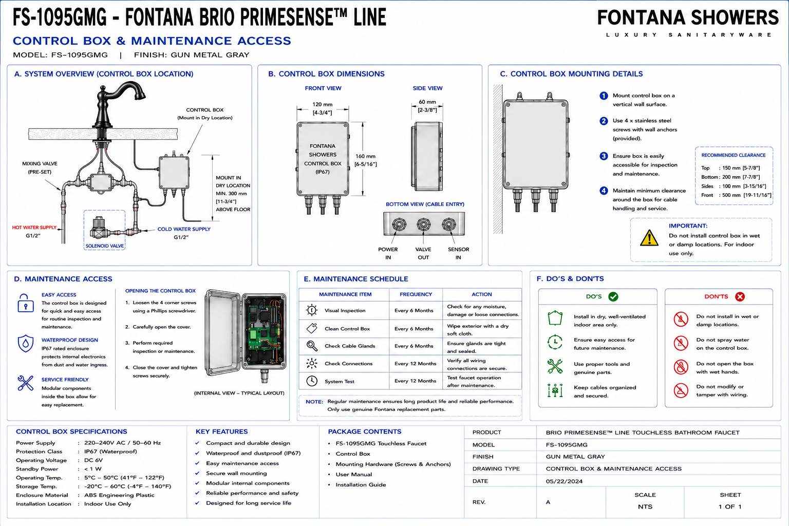
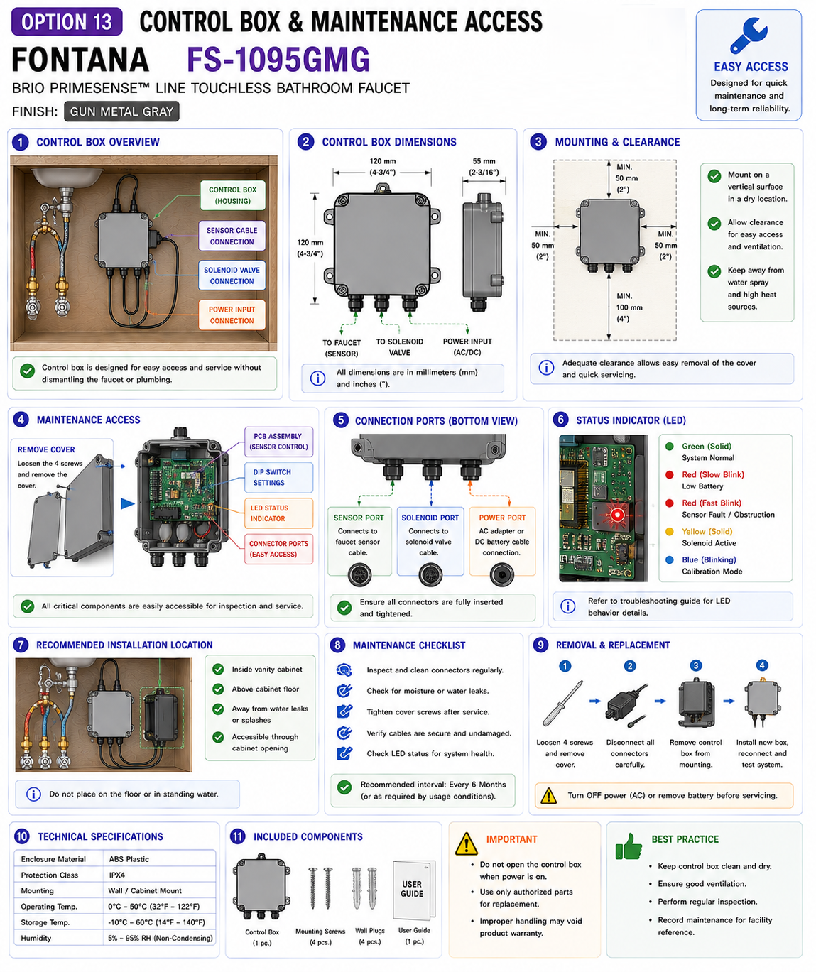
The control-box drawing should show the electronic controller as part of the
complete under-counter faucet system. The drawing should identify the controller
enclosure, mounting surface, power input, sensor connection, solenoid connection,
cable-routing paths, adjacent mixing and water-control components, basin envelope,
drain assembly and required maintenance-access zone. Components should be arranged
so routine inspection and replacement can occur from the cabinet opening without
disturbing permanent countertop or basin construction.
Complete Control Box & Maintenance Access Detail
Show the controller centered within the under-counter equipment
arrangement, together with its power, sensor and solenoid connections.
Clearly identify the unobstructed technician-access zone and the
controller's relationship to plumbing and drainage components.
Electronic Control Box
Identify the primary electronic controller responsible for processing
infrared sensor input and commanding automatic water operation.
Controller Mounting Surface
Show the controller secured to a stable cabinet wall, service panel
or other approved support surface rather than hanging unsupported
from its wiring.
Controller Mounting Orientation
Position the enclosure according to the approved installation
arrangement while keeping cable connections visible and accessible
from the cabinet service opening.
Controller Mounting Height
Locate the controller above the lowest cabinet level where practical
to reduce exposure to cleaning water, condensation and minor
plumbing leakage.
Power Input Connection
Identify the designated controller power input and show its
relationship to the selected AC or DC power configuration.
AC Power Coordination
For an AC-powered installation, show the approved power component
and its route to the controller while maintaining appropriate
separation from water connections.
DC Battery Coordination
For a battery-powered installation, show the 6V DC battery enclosure
in an accessible dry location adjacent to, but not obstructing, the
controller service zone.
Infrared Sensor Connection
Show the faucet sensor cable entering the designated controller
connection. The connector should remain visible for diagnostic
inspection and sensor testing.
Solenoid Valve Connection
Identify the controller output connected to the automatic solenoid
valve. The cable route should remain clear of hydraulic fittings and
moving cabinet hardware.
Sensor Cable Route
Route the sensor cable from the faucet body to the controller without
sharp bends, excessive tension or contact with abrasive cabinet edges.
Solenoid Cable Route
Show a direct, protected path from the controller to the solenoid
valve while avoiding unnecessary cable loops around plumbing
components.
Power Cable Route
Route the selected power connection independently from water hoses
and drain piping wherever practical and protect it from cabinet
hardware.
Cable Connector Access
Maintain clear finger access to controller connectors so cables can
be disconnected without removing the controller from its mounting
surface.
Cable Strain Relief
Support wiring so hanging cable weight is not transferred directly
to the controller's electrical connectors.
Cable Service Loop
Where appropriate, provide modest service loops that allow the
controller to be inspected or repositioned slightly without pulling
on the sensor, power or solenoid connectors.
Protected Cabinet Penetration
Where cables pass through cabinet panels, show protected penetrations
or grommets to prevent abrasion against sharp material edges.
Dry Electrical Zone
Reserve a defined dry area for the control box and associated
electrical connections, separated from locations where plumbing
leakage is reasonably foreseeable.
Water-Supply Exclusion Zone
Do not locate the controller directly beneath G1/2 water connections,
angle stops, flexible hose unions, mixing-valve joints or other
pressurized plumbing fittings.
Solenoid Hydraulic Separation
Keep the electronic controller sufficiently separated from the
solenoid's inlet and outlet water connections to reduce exposure
if a hydraulic fitting requires service.
Drain Exclusion Zone
Do not position the control box directly beneath the lavatory
tailpiece, P-trap or other drainage joints that may release water
during maintenance.
Cabinet Floor Clearance
Keep the electronic controller and loose electrical connectors above
the cabinet floor where practical to reduce exposure to standing
water.
Front Service Clearance
Provide unobstructed working space immediately in front of the
controller so technicians can inspect, disconnect and test the
electronic system.
Side Service Clearance
Maintain sufficient lateral clearance for cable manipulation,
fastener access and controller removal without interference from
cabinet framing or plumbing.
Vertical Service Clearance
Provide sufficient space above and below the controller for cable
routing, connector removal and enclosure servicing.
Controller Removal Path
Show a clear removal direction so the control box can be detached
from its support and removed through the cabinet opening without
disturbing the basin or countertop.
Fastener Access
Mounting screws, clips or brackets should remain accessible with
ordinary service tools after the complete faucet installation has
been commissioned.
Component Identification
Clearly identify the controller, power supply, sensor cable and
solenoid cable so technicians can distinguish electrical components
during troubleshooting.
Maintenance Working Envelope
Show a clearly defined service envelope around the control box that
should remain free of stored items, plumbing obstructions and
permanent cabinet components.
Finished Control Box Arrangement
The final installation should present a securely mounted controller,
organized wiring, protected electrical connections, clear plumbing
separation and an unobstructed maintenance-access path.
Engineering note:
Do not conceal the touchless-faucet controller behind permanent millwork,
inaccessible wall construction or fixed plumbing assemblies. The exact
controller enclosure, connector orientation, power arrangement and mounting
method should be verified against the supplied product components and
approved FontanaShowers installation documentation before final cabinet
coordination.
Required Control Box Drawing Views
Front Under-Counter Elevation
Show the control box, battery or AC power component, solenoid valve,
mixing valve, water hoses, drain and maintenance-access envelope.
Side Cabinet Section
Show controller depth, mounting plane, basin envelope, plumbing
clearance and the required front service-access space.
Controller Connection Diagram
Show the power input, infrared sensor connection and solenoid-valve
output as separate identified connections.
Maintenance Clearance Plan
Show the horizontal service envelope required around the controller,
power supply and cable connections.
Cable Routing Detail
Show sensor, solenoid and power wiring routes together with protected
penetrations, service loops and cable-support locations.
Controller Removal Detail
Show the direction and clearance necessary to release the controller
from its mounting surface and remove it for replacement.
Recommended Control Box Installation Sequence
1. Review Under-Counter Layout
Confirm the final basin, drain, water-supply, mixing-valve, solenoid
and power-component locations before positioning the controller.
2. Select Dry Service Location
Choose a controller position away from foreseeable plumbing drip
paths and standing-water locations.
3. Verify Cable Reach
Confirm the sensor, solenoid and power leads can reach the selected
controller location without extension, stretching or excessive
tension.
4. Verify Service Envelope
Confirm the proposed controller location leaves sufficient working
space for connector access, testing and future component removal.
5. Secure the Controller
Mount the controller to a stable support surface using the approved
fastening arrangement.
6. Route Sensor Wiring
Route the faucet sensor cable to the controller while avoiding
sharp cabinet edges and plumbing components.
7. Route Solenoid Wiring
Route the solenoid cable through a protected path and maintain
clearance from hydraulic fittings.
8. Connect Power
Connect the selected approved AC or DC power configuration to the
designated controller input.
9. Connect Sensor
Connect the infrared sensor lead to the corresponding controller
port and verify the connection is fully seated.
10. Connect Solenoid Valve
Connect the automatic water-control valve to the designated
controller output.
11. Organize & Support Cables
Secure excess cable without over-tightening and preserve reasonable
service loops at the controller.
12. Perform Access Check
Confirm every connector and mounting fastener can be reached after
all plumbing and cabinet components are complete.
Maintenance Access Coordination
Direct Visual Access
The controller should be visible from the normal cabinet service
opening without requiring removal of unrelated building components.
Connector Access
Technicians should be able to reach power, sensor and solenoid
connectors individually for diagnostic testing.
Fastener Access
Maintain tool clearance around mounting fasteners so the controller
can be removed without disturbing plumbing.
Cable Inspection
Keep sufficient wiring visible so pinching, abrasion, moisture
exposure and loose connectors can be identified during inspection.
Component Replacement
The maintenance arrangement should permit controller replacement
without removing the faucet body, basin or countertop.
Facility Access
Do not use the controller service envelope as permanent storage
space after project turnover.
Control Box & Plumbing Coordination
Angle Stop Clearance
Keep the controller away from hot- and cold-water shutoff valves so
those valves can be operated or replaced independently.
Mixing Valve Clearance
Maintain enough separation from the mixing valve to permit
temperature adjustment and hydraulic servicing.
Solenoid Valve Clearance
Keep hydraulic fittings on the automatic valve outside the
controller's electrical service envelope.
Supply Hose Clearance
Do not route flexible water hoses across the face of the controller
or over its electrical connectors.
Drain Trap Clearance
Keep the P-trap and removable drainage fittings clear of the
controller and its wiring.
Independent Maintenance
Arrange hydraulic and electronic components so either system can be
serviced with minimal disturbance to the other.
Control Box Commissioning Tests
Power Verification
Confirm the selected AC or DC power source is correctly connected
to the controller before testing faucet operation.
Sensor Input Test
Activate the infrared detection zone and verify the controller
responds consistently to sensor input.
Solenoid Output Test
Verify the controller commands the solenoid valve to open and close
in response to sensor activation.
Connector Security Test
Inspect all controller plugs and verify they are fully seated and
not under cable tension.
Repeated-Cycle Test
Run multiple touchless operating cycles and verify stable controller,
sensor and valve performance.
Final Access Inspection
After commissioning, verify that testing did not leave cables,
hoses or stored materials obstructing the required maintenance zone.
Control Box Troubleshooting Considerations
No Faucet Response
Check controller power, power connector, sensor connection and
available power source before replacing the controller.
Sensor Activates but No Water
Check the controller-to-solenoid connection and verify that the
solenoid valve and hydraulic supply are operational.
Intermittent Operation
Inspect loose connectors, cable strain, damaged wiring, sensor
conditions and power stability.
Moisture Near Controller
Isolate the system as appropriate and identify the source of
moisture before returning the electronic controls to normal service.
Damaged Cable
Inspect wiring at cabinet penetrations, mounting points and moving
hardware for abrasion, pinching or cuts.
Inaccessible Controller
Remove movable obstructions and revise cabinet organization where
necessary so the controller remains serviceable throughout the
facility lifecycle.
Preventive Maintenance Access Checklist
-
Inspect controller mounting:
Verify the enclosure remains securely fastened to its support surface.
-
Inspect power connection:
Check the selected AC or DC connection for secure engagement and visible damage.
-
Inspect sensor connector:
Confirm the sensor lead remains fully seated and free from cable strain.
-
Inspect solenoid connector:
Check the valve-control cable and connector for secure engagement.
-
Inspect cable routing:
Look for abrasion, pinching, excessive bends or contact with moving cabinet hardware.
-
Inspect for moisture:
Check the controller area for evidence of supply or drainage leakage.
-
Maintain dry zone:
Do not store cleaning liquids or wet materials around the electronic controller.
-
Maintain service envelope:
Keep the working area in front of and around the controller unobstructed.
-
Verify functional response:
Run multiple touchless activation cycles after maintenance.
-
Document service:
Record controller, sensor, solenoid or power-component replacements where required by facility procedures.
Control Box & Service Component Identification
-
Electronic control box:
Primary electronic module coordinating touchless faucet operation.
-
Power input:
Controller connection receiving the approved AC-derived or DC battery supply.
-
Infrared sensor input:
Connection receiving activation signals from the faucet sensor.
-
Solenoid output:
Controller connection operating the automatic water-control valve.
-
Sensor cable:
Low-voltage lead connecting the faucet sensor to the controller.
-
Solenoid cable:
Low-voltage lead connecting the controller to the automatic valve.
-
Power cable:
Connection between the selected power source and controller.
-
Mounting bracket / fastener:
Hardware securing the controller to the approved support surface.
-
Protected penetration:
Cabinet opening or grommet protecting control wiring from abrasion.
-
Dry electrical zone:
Area reserved for electronic components outside normal plumbing drip paths.
-
Maintenance-access envelope:
Unobstructed working area required for inspection and servicing.
-
Controller removal path:
Clear route allowing the electronic module to be removed without dismantling permanent construction.
FontanaShowers Installation and Specification Resources
Professional Engineering & Facility References
Project verification:
This control-box and maintenance-access resource is intended for architectural,
electrical, plumbing, millwork, commissioning and facility-maintenance
coordination and does not replace approved manufacturer instructions or project
submittals. The electrical engineer, plumbing engineer, architect, millwork
coordinator, licensed installer and commissioning technician should verify the
actual control-box enclosure, mounting orientation, power connection, sensor
input, solenoid output, cable routing, cabinet penetrations, water and drain
separation, service clearances and component-removal path against the supplied
FS-1095GMG components before final installation and project turnover.
|
|
|