Fontana Touchless Faucets™ | Architectural, BIM and MEP Coordination Resource
Fontana Brio PrimeSense™ Line FS-1095GMG Gun Metal Gray Touchless Bathroom Faucet:
BIM / MEP Coordination Drawing
This BIM and MEP coordination resource is intended to support architects,
plumbing engineers, electrical engineers, BIM managers, VDC coordinators,
interior designers, millwork fabricators, contractors, installers and facility
managers coordinating the Fontana Brio PrimeSense™ Line FS-1095GMG touchless
bathroom faucet within commercial and institutional projects. The drawing
coordinates the visible faucet and basin with the concealed mounting stem,
G1/2 water supplies, hot- and cold-water isolation valves, mixing valve,
solenoid valve, electronic control box, AC or DC power components, infrared
sensor wiring, drainage system, cabinet construction and required service
access zones.
Fontana Brio PrimeSense™ Line FS-1095GMG Touchless Bathroom Faucet
The FS-1095GMG is a deck-mounted touchless faucet requiring coordinated
architectural, plumbing, electrical and millwork interfaces. A complete
BIM or MEP coordination model should represent not only the visible faucet
body but also the concealed water-control, power and maintenance systems
below the countertop so conflicts can be identified before fabrication
and field installation.
-
Model:
FS-1095GMG
-
Product type:
Touchless bathroom faucet
-
Installation:
Single-hole deck mount
-
Finish:
Gun Metal Gray
-
Water connection:
G1/2"
-
Water supplies:
Hot and cold
-
Temperature control:
Under-counter mixing arrangement
-
Automatic water control:
Solenoid valve
-
Electronic control:
Under-counter control box
-
Sensor:
Infrared automatic activation
-
Sensor range:
Approximately 16–32 cm adjustable
-
AC power option:
220–240V AC
-
DC power option:
6V DC using 4 × AA batteries
-
Flow rate:
1.2 GPM [4.5 L/min] at 60 PSI
-
Coordination disciplines:
Architecture, plumbing, electrical, millwork and BIM/VDC
Required BIM / MEP Coordination Drawing Package
The BIM and MEP coordination package should combine architectural fixture
placement, plumbing rough-in, hydraulic control components, electrical power,
low-voltage wiring, cabinet geometry and service-access requirements within
one coordinated model. The faucet should be modeled as a system rather than
as a single decorative object so clashes involving the basin, drain, supply
lines, controller, solenoid valve, cabinet rails, shelves and power
infrastructure can be reviewed before construction.
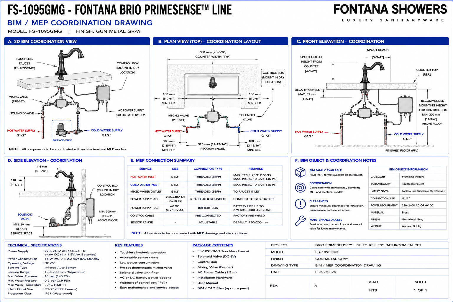
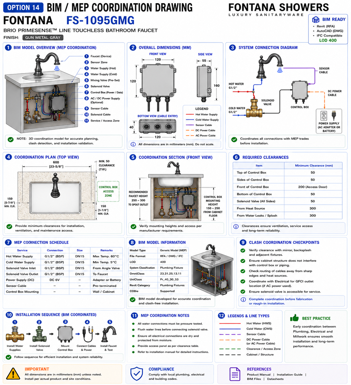
Complete BIM / MEP Coordination View
Shows the FS-1095GMG faucet, countertop, basin, mounting stem,
G1/2 water connections, mixing valve, solenoid valve, controller,
power components, sensor wiring, drain assembly and service-access
zones in one coordinated model.
Architectural Faucet Position
Model the faucet centerline accurately relative to the basin,
backsplash, countertop edges and adjacent deck-mounted accessories.
The architectural model should establish the primary visible fixture
location used by all MEP disciplines.
Single-Hole Countertop Penetration
Include the faucet mounting penetration within the countertop model
and coordinate the opening with countertop thickness, basin cutout,
stone reinforcement and under-counter support construction.
Faucet Mounting Stem
Model the concealed mounting stem below the countertop to identify
potential conflicts with undermount basin flanges, structural rails
and cabinet elements.
Basin Geometry
Use the actual selected basin dimensions rather than a generic
lavatory placeholder. Basin depth and underside geometry affect
available space for the faucet's concealed components.
Basin Cutout
Model the countertop cutout and hidden basin flange so the faucet
hole, mounting hardware and plumbing components can be checked for
interference.
Basin Mounting Hardware
Include undermount clips, brackets or support rails where their
locations could interfere with the faucet shank, hoses or control
equipment.
G1/2 Hot-Water Supply
Show the project hot-water branch terminating at an accessible
G1/2 isolation valve within the cabinet equipment zone.
G1/2 Cold-Water Supply
Show the cold-water branch and isolation point coordinated with
the cabinet layout, drain and controller.
Hot-Water Isolation Valve
Model the angle stop with sufficient access for operation and future
replacement. Avoid placing cabinet partitions or controller equipment
directly in front of the valve.
Cold-Water Isolation Valve
Show the cold-water shutoff as a maintainable plumbing component with
an unobstructed service path.
Braided Supply Hose Paths
Model representative hose-routing envelopes between the angle stops,
mixing assembly and automatic valve to prevent cabinet framing or
drawers from occupying required connection space.
Under-Counter Mixing Valve
Show the mixing valve as a discrete serviceable component with hot,
cold and mixed-water connections and sufficient clearance for
maintenance.
Solenoid Valve
Model the electronically controlled water valve downstream of the
mixing assembly and preserve clearance around its inlet, outlet and
electrical connector.
Water-Flow Direction
Identify the hydraulic sequence from the building supplies through
the mixing valve and solenoid valve to the faucet inlet.
Electronic Control Box
Model the controller as a maintainable under-counter component rather
than a symbolic annotation. Its actual envelope should be coordinated
with plumbing, cabinetry and service access.
Controller Mounting Zone
Reserve a stable vertical mounting surface or approved support area
for the controller and prevent other disciplines from occupying that
zone.
AC Power Zone
Where AC operation is selected, identify the approved power connection,
adapter or transformer location and maintain separation from plumbing
drip zones.
DC Battery Zone
Where battery power is selected, model the battery enclosure and
its removal path so battery replacement remains possible after
cabinet completion.
Sensor Cable Route
Show the low-voltage route from the faucet sensor to the controller
and prevent clashes with cabinet hinges, drawer slides and sharp
structural edges.
Solenoid Control Cable
Show the cable route from the controller to the solenoid valve and
coordinate it separately from water hoses where practical.
Power Cable Routing
Model the power cable path and any cabinet penetrations required to
reach the controller without crossing high-risk plumbing areas.
Protected Cable Penetrations
Show required grommets or protected openings where low-voltage or
power cables pass through cabinet panels or support construction.
Drain Tailpiece
Model the vertical drain connection beneath the basin because its
position frequently conflicts with faucet electronics and valve
equipment.
P-Trap Envelope
Include the complete trap geometry and removal path so the drainage
system remains independently serviceable.
Plumbing Service Envelope
Reserve working clearance around angle stops, hose connections,
mixing valve and solenoid valve so they can be serviced without
removing the controller.
Electrical Service Envelope
Reserve a separate service zone around the control box, power
components and electrical connectors.
Controller Removal Path
Model the clear space needed to detach and remove the electronic
controller from the cabinet without removing the sink or countertop.
Solenoid Removal Path
Show sufficient working room to isolate, disconnect and remove the
automatic water-control valve.
Cabinet Door Access
Coordinate the door opening and clear service approach with all
concealed faucet components.
Drawer Interference Zone
Where drawers are present, model the complete drawer-box and slide
envelope so moving components cannot strike hoses, valves, wiring
or the controller.
Cabinet Shelf Interference
Fixed shelves should not occupy required valve, controller or
battery-service zones unless removable access provisions are provided.
Countertop Support Rails
Coordinate steel angles, plywood rails and other countertop supports
with the faucet stem, sensor cable and service-access path.
Dry Electrical Zone
Represent a no-plumbing-overhead region around the controller and
power components to reduce exposure to leakage.
Clash Detection Envelope
Include clearances around critical components in clash-detection
workflows rather than checking only physical component geometry.
Finished Coordinated Model
The final BIM model should represent an installable, maintainable
system in which the architectural, plumbing, electrical and millwork
elements coexist without physical or service-access conflicts.
Engineering note:
BIM coordination should not stop at zero-clearance clash detection.
Maintenance, valve operation, connector access, hose bend radius, controller
removal and battery replacement require working clearances beyond the
physical component envelope. Verify all final geometry against the approved
FontanaShowers submittal and the actual project basin and cabinet design.
Required BIM / MEP Drawing Views
3D Isometric Coordination View
Show the faucet, basin, supplies, valves, controller, drain and
cabinet construction in one three-dimensional coordination view.
Front MEP Elevation
Show supply valves, mixing valve, solenoid, controller, drain and
service zones below the lavatory.
Side Cabinet Section
Show the basin depth, faucet shank, MEP components, cabinet depth
and front maintenance approach.
Under-Counter Plan
Show hidden basin geometry, drain, valves, controller, hoses,
wiring and cabinet support construction.
Plumbing Riser / Flow Diagram
Show the hot and cold supply sequence through the mixing and
automatic valve assemblies to the faucet.
Electrical Control Diagram
Show the power source, controller, sensor and solenoid-valve
connections as a coordinated control schematic.
BIM Object / Family Coordination Requirements
Product Identity
The BIM object should clearly identify the manufacturer, product
name and FS-1095GMG model reference.
Finish Parameter
Include Gun Metal Gray as the specified finish parameter within the
faucet object or project schedule.
Mounting Type
Identify the object as a single-hole deck-mounted fixture so
countertop coordination is explicit.
Plumbing Connector
Represent the G1/2 water connection requirement within the plumbing
coordination data where the BIM authoring platform supports connector
information.
Power Parameter
Include the selected AC or DC power configuration in the project
schedule rather than leaving the power method undefined.
Maintenance Clearance
Use a visibility-controlled clearance volume or equivalent modeling
method to represent required maintenance access in coordination
views.
Architectural Coordination
Countertop Thickness
Coordinate the complete countertop build-up with the available faucet
mounting stem and underside retaining hardware.
Backsplash Clearance
Maintain sufficient rear clearance for faucet installation, sensor
operation and routine cleaning.
Mirror Coordination
Check the faucet height and sensor environment against mirrors,
frames, shelves and other rear-wall elements.
Basin Alignment
Coordinate the spout outlet and water stream with the usable basin
capture zone.
Adjacent Accessories
Check soap dispensers and other countertop accessories for both
above-deck and below-deck interference.
Cabinet Access
The millwork design should preserve front access to all concealed
faucet components.
Plumbing MEP Coordination
Hot-Water Branch
Coordinate branch piping and the final isolation valve with the
actual under-counter equipment envelope.
Cold-Water Branch
Coordinate the cold-water connection so the valve remains accessible
and the hose route is not obstructed.
Mixing Assembly
Maintain adequate space for the mixing valve and its three hydraulic
connections.
Solenoid Assembly
Maintain hydraulic and electrical service access around the automatic
water-control valve.
Drain Routing
Route the drain to avoid the controller, solenoid, mixing valve and
faucet mounting stem.
Maintenance Isolation
The faucet should be isolatable without shutting down unrelated
restroom fixtures.
Electrical MEP Coordination
AC Power Coordination
Where AC power is selected, coordinate the 220–240V supply and
approved power component with the under-counter dry electrical zone.
DC Battery Coordination
Where DC operation is selected, preserve access for replacement of
the four-AA battery pack.
Sensor Wiring
Coordinate the sensor cable from the faucet to the controller without
crossing moving cabinet hardware.
Solenoid Wiring
Maintain a direct serviceable route from the controller to the
solenoid valve.
Controller Access
Reserve working clearance around all controller connectors and
mounting fasteners.
Dry Zone Coordination
Keep electrical equipment outside direct drip paths from plumbing
and drain connections.
Millwork / Cabinet Coordination
Cabinet Partitions
Do not place permanent partitions through the controller, valve or
hose service zones.
Drawers
Model full drawer travel and slide hardware to ensure they cannot
contact faucet components.
Shelves
Shelves should remain outside critical service envelopes unless they
are intentionally removable.
Door Hardware
Check hinge projection and door swing against hoses, wiring and
controller locations.
Countertop Supports
Keep countertop brackets and structural rails clear of the faucet
mounting stem and cable drop zone.
Removable Access
Where cabinet geometry limits direct access, provide a removable
panel large enough for component inspection and replacement.
BIM Clash Detection Priorities
Faucet Stem vs Basin
Check the mounting stem and retaining hardware against the hidden
basin flange and bowl geometry.
Supply Valves vs Cabinet
Check angle stops and hose connections against partitions, drawers
and support rails.
Mixing Valve vs Trap
Verify the mixing assembly does not occupy the trap-removal path.
Solenoid vs Drain
Check the automatic valve and its service envelope against drainage
piping.
Controller vs Plumbing
Verify water-supply and drain components do not occupy the dry
electrical zone.
Service Zone vs Millwork
Run clash detection against required maintenance volumes as well as
the physical product components.
Recommended BIM / MEP Coordination Sequence
1. Confirm Product Selection
Verify the final FS-1095GMG model, finish and power configuration
before detailed coordination begins.
2. Insert Actual Basin
Use the exact project basin geometry and mounting information.
3. Establish Faucet Centerline
Coordinate the faucet mounting location with the basin and
countertop.
4. Model Water Supplies
Place the hot and cold supply branches and accessible shutoff valves.
5. Model Hydraulic Controls
Place the mixing and solenoid valves with representative connection
and service envelopes.
6. Model Drainage
Coordinate the drain and trap without occupying valve or controller
service zones.
7. Model Controller & Power
Place the controller and selected AC or DC power equipment within
a dry electrical zone.
8. Model Cable Routes
Coordinate sensor, solenoid and power wiring with cabinetry and
plumbing.
9. Add Maintenance Envelopes
Model required service-clearance volumes around valves, controller,
battery box and mounting hardware.
10. Run Clash Detection
Check both hard component clashes and soft maintenance-clearance
conflicts.
11. Resolve Discipline Conflicts
Update architectural, plumbing, electrical or millwork geometry
until the installation is physically and operationally coordinated.
12. Freeze Coordinated Layout
Issue the coordinated model and drawings for countertop fabrication,
MEP rough-in and final installation.
BIM / MEP Coordination Notes
-
Use approved product dimensions:
Do not rely on generic sensor-faucet family geometry for final coordination.
-
Model concealed components:
The mixing valve, solenoid, controller and power equipment are part of
the coordinated system.
-
Coordinate actual basin geometry:
Basin depth and hidden mounting details affect all under-counter components.
-
Model service clearances:
Zero physical clash does not guarantee maintainability.
-
Coordinate hot and cold supplies:
Preserve independent access to both G1/2 isolation points.
-
Protect electrical zones:
Keep controller and power components outside foreseeable plumbing drip paths.
-
Maintain trap-removal access:
The drainage system should remain independently serviceable.
-
Coordinate cabinet movement:
Check drawers, hinges and doors through their full range of motion.
-
Coordinate power selection:
Identify whether the project uses AC or DC power before construction documents are finalized.
-
Verify field installation:
Compare the installed condition with the coordinated model before project closeout.
BIM / MEP Component Identification
-
Touchless faucet body:
Visible FS-1095GMG deck-mounted fixture.
-
Mounting hole:
Countertop penetration receiving the faucet assembly.
-
Mounting stem:
Concealed threaded assembly below the countertop.
-
Hot-water supply:
G1/2 project water connection feeding the mixing assembly.
-
Cold-water supply:
G1/2 project cold-water connection.
-
Mixing valve:
Under-counter component combining hot and cold water.
-
Solenoid valve:
Electronically controlled automatic water valve.
-
Electronic controller:
Module receiving sensor input and operating the solenoid.
-
Sensor cable:
Low-voltage wiring between faucet and controller.
-
Solenoid cable:
Control wiring between controller and valve.
-
AC power component:
Approved power equipment used when AC operation is selected.
-
Battery enclosure:
6V DC power source using four AA batteries when DC operation is selected.
-
Drain tailpiece:
Vertical basin waste connection.
-
P-trap:
Drainage component requiring independent removal clearance.
-
Millwork envelope:
Cabinet structure surrounding concealed plumbing and controls.
-
Maintenance envelope:
Reserved clearance volume required for servicing the faucet system.
FontanaShowers BIM, Installation and Specification Resources
Professional BIM, Engineering and Facility References
Project verification:
This BIM / MEP coordination drawing is intended for architectural, plumbing,
electrical, millwork, VDC, fabrication and facility-maintenance coordination
and does not replace approved manufacturer installation instructions or project
submittals. The architect, plumbing engineer, electrical engineer, BIM/VDC
coordinator, millwork fabricator and licensed installer should verify the actual
FS-1095GMG product geometry, mounting opening, countertop construction, basin
model, G1/2 water connections, mixing valve, solenoid valve, controller,
selected AC or DC power system, cable routing, drain geometry, cabinet
construction, maintenance envelopes and locally adopted project requirements
before fabrication and installation.
|
|
|