Fontana Touchless Faucets™ | Architectural and Engineering Resource
Fontana Brio PrimeSense™ Line FS-1095GMG Gun Metal Gray Touchless Bathroom Faucet:
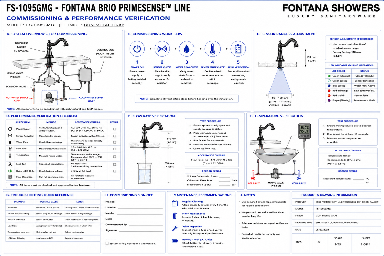
Commissioning Performance Verification
This commissioning-performance verification resource is intended to support
architects, plumbing engineers, electrical engineers, MEP coordinators,
commissioning agents, contractors, installers and facility managers verifying
the installed performance of the Fontana Brio PrimeSense™ Line FS-1095GMG
touchless bathroom faucet. The verification process evaluates hydraulic
connections, sensor response, solenoid-valve operation, AC or DC power,
automatic shut-off, water-stream alignment, basin splash performance,
temperature delivery, leakage, control-box accessibility and final maintenance
readiness before project turnover.
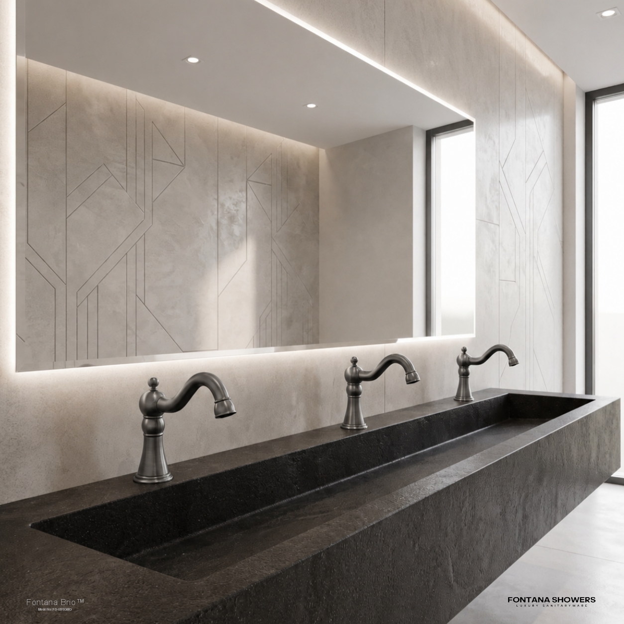
Fontana Brio PrimeSense™ Line FS-1095GMG Touchless Bathroom Faucet
The FS-1095GMG is a deck-mounted automatic faucet that should be
commissioned as an integrated hydraulic and electronic system rather
than as an isolated plumbing fixture. Final verification should confirm
that the infrared sensor, controller, solenoid valve, power source,
G1/2 water connections, mixing arrangement and basin geometry operate
together reliably under actual project conditions.
-
Model:
FS-1095GMG
-
Product type:
Touchless bathroom faucet
-
Installation:
Single-hole deck mount
-
Finish:
Gun Metal Gray
-
Sensor:
Infrared automatic activation
-
Sensor range:
Approximately 16–32 cm adjustable
-
Water connection:
G1/2"
-
Automatic water control:
Solenoid valve
-
Electronic control:
Under-counter control box
-
AC power option:
220–240V AC
-
DC power option:
6V DC using 4 × AA batteries
-
Flow rate:
1.2 GPM [4.5 L/min] at 60 PSI
-
Verification scope:
Hydraulic, sensor, electrical and service-access performance
-
Application:
Commercial and institutional washrooms
Required Commissioning Performance Verification Package
The commissioning drawing should document the complete installed faucet
system and identify each verification point used during startup and project
turnover. The drawing should show the faucet, basin, sensor zone, water
stream, G1/2 supplies, mixing valve, solenoid valve, controller, selected
power source, drain, service-access area and test points required to confirm
functional performance.
Complete Commissioning Verification Overview
Shows the entire FS-1095GMG installation with numbered test points
for water supply, sensor operation, solenoid response, power,
water-stream alignment, leakage inspection and maintenance access.
Product Identity Verification
Confirm that the installed fixture matches the specified
FS-1095GMG model and Gun Metal Gray finish before functional
commissioning begins.
Faucet Mounting Verification
Confirm the faucet body is secure, vertical and correctly aligned
with the basin. Check for rocking, loose mounting hardware or
visible movement at the countertop.
Countertop Seal Verification
Inspect the faucet base and gasket interface to confirm the fixture
is seated evenly and the countertop penetration is appropriately
protected against moisture.
G1/2 Connection Verification
Verify all G1/2 water-supply connections are correctly assembled,
compatible and fully secured before operating the faucet.
Hot-Water Supply Verification
Confirm the hot-water branch is connected to the designated inlet
and the isolation valve is fully operational and accessible.
Cold-Water Supply Verification
Verify the cold-water branch is connected correctly and that its
isolation valve can be operated independently.
Mixing Valve Verification
Confirm the under-counter mixing assembly receives the correct hot
and cold connections and supplies an appropriate mixed-water
temperature to the automatic valve.
Solenoid Valve Orientation
Verify the automatic valve is installed in the intended water-flow
direction and that inlet and outlet connections are correctly
identified.
Solenoid Valve Opening Test
Activate the infrared sensor and verify the solenoid opens promptly
and allows water to flow without hesitation or abnormal noise.
Solenoid Valve Closing Test
Remove hands from the sensing zone and verify the solenoid closes
reliably and stops water flow without continued dripping or delayed
shut-off.
Controller Power Verification
Confirm the electronic control box receives stable power through
the selected AC or DC configuration and remains operational through
repeated activation cycles.
AC Power Verification
Where AC power is used, verify the approved power connection,
adapter or transformer is secure, dry and accessible.
DC Battery Verification
Where battery operation is selected, verify all four AA batteries
are correctly installed, oriented and securely enclosed.
Sensor Power-Up Test
Verify the sensor initializes correctly after the controller is
energized and does not produce uncontrolled water flow during
startup.
Sensor Detection Test
Move hands naturally into the washing zone and confirm the faucet
activates consistently within the calibrated infrared detection
field.
Minimum Detection Test
Verify the faucet responds when hands enter the near portion of the
intended sensing zone without requiring contact with the fixture.
Maximum Detection Test
Check the outer edge of the detection field and confirm the sensor
does not extend unnecessarily into adjacent circulation or accessory
areas.
Standby False-Trigger Test
With no user present, observe the faucet and verify the basin,
backsplash or nearby reflective surfaces do not cause unintended
activation.
Left-Side Approach Test
Approach the wash zone from the left and verify reliable activation
without excessive sensor spread.
Right-Side Approach Test
Repeat the activation test from the right side and confirm the
detection field is centered on the usable handwashing zone.
Water-Stream Alignment
Verify the water stream enters the intended basin capture area and
does not strike the rim, countertop or drain in a manner that causes
excessive splash.
Stream Landing Point
Observe where the water first contacts the basin and confirm the
landing point is suitable for comfortable handwashing and splash
control.
Basin Splash Verification
Run multiple handwashing cycles and inspect the countertop, user
approach area and backsplash for unacceptable splash.
Flow Performance Verification
Confirm the faucet provides a stable and usable stream without
pulsation, excessive restriction or irregular discharge.
Temperature Verification
Check the mixed-water temperature at the faucet outlet and confirm
it is appropriate for the intended project application.
Static Leak Test
With the water supplies pressurized and the faucet inactive, inspect
all G1/2 fittings, hoses, mixing-valve connections and solenoid
connections for leakage.
Dynamic Leak Test
Operate the faucet repeatedly and inspect hydraulic connections
while water is flowing through the complete system.
Automatic Shut-Off Verification
Verify water flow terminates correctly after the user's hands leave
the detection field and that continuous activation protection
operates as intended.
Repeated-Cycle Verification
Run multiple consecutive activation and deactivation cycles to
confirm consistent sensor, controller and solenoid performance.
Control Box Access Verification
Confirm the controller remains visible and accessible after all
cabinet components, shelves and plumbing have been installed.
Solenoid Service Access
Verify the automatic valve can be isolated, disconnected and
removed without removing the basin or countertop.
Battery Replacement Access
Where DC operation is used, verify the battery enclosure can be
opened and all four batteries can be replaced from the normal
service position.
Final Maintenance Access Verification
Confirm that shutoff valves, mixing valve, solenoid, controller,
power components, connectors and mounting hardware remain accessible
for future maintenance.
Final Acceptance Condition
The faucet should be accepted only after hydraulic, sensor,
electrical, splash-control and service-access performance has been
verified and any deficiencies have been corrected.
Engineering note:
Commissioning should be performed with the final basin, countertop,
backsplash, power configuration, plumbing pressure and surrounding finishes
in place. Sensor behavior and splash performance observed before completion
of the washroom may not represent the final operating condition.
Required Commissioning Verification Views
Complete System Elevation
Show the faucet, basin, water supplies, valves, controller,
power source and numbered commissioning test points.
Sensor Verification View
Show the infrared sensing field and representative hand positions
used during commissioning.
Hydraulic Verification Diagram
Show hot and cold water, mixing valve, solenoid valve and faucet
with flow-direction arrows and inspection points.
Electrical Verification Diagram
Show the selected power source, controller, sensor and solenoid
connections used during electrical commissioning.
Basin Splash Test View
Show the water-stream path, basin landing point and areas monitored
for splash during functional testing.
Maintenance Access View
Show all concealed components together with the working-clearance
zones verified before project turnover.
Recommended Commissioning Sequence
1. Confirm Installation Complete
Verify the faucet, basin, plumbing, controller, solenoid, selected
power source and cabinet components are fully installed.
2. Inspect Mechanical Mounting
Check faucet alignment, mounting hardware and countertop interface
before pressurizing or energizing the system.
3. Flush the Water Supply
Flush project piping before final functional testing to remove
construction debris from the automatic valve system.
4. Pressurize the Hydraulic System
Open water supplies gradually and inspect all concealed connections
for leakage.
5. Energize the Controller
Connect the approved AC or DC power source and verify stable
controller operation.
6. Verify Sensor Detection
Test the infrared sensor from the normal user approach and adjust
the detection zone where necessary.
7. Verify Solenoid Operation
Confirm the automatic valve opens and closes consistently in
response to controller commands.
8. Check Stream Alignment
Confirm the water stream lands within the intended basin area and
does not produce excessive splash.
9. Verify Temperature
Check delivered mixed-water temperature and confirm the upstream
mixing arrangement is operating as intended.
10. Run Repeated Cycles
Operate the faucet repeatedly to verify stable sensor, controller,
solenoid and hydraulic performance.
11. Verify Service Access
Check that maintenance personnel can reach all concealed components
without removing permanent construction.
12. Record Final Acceptance
Document final performance, adjustments, deficiencies corrected and
accepted operating condition for project turnover.
Sensor Commissioning Verification
Detection Range
Verify the final infrared sensing zone provides comfortable user
activation without unnecessary extension beyond the basin.
Activation Consistency
Test multiple natural hand positions and confirm reliable activation
throughout the intended washing area.
False Activation
Observe the faucet in standby and confirm reflective basin,
backsplash or mirror surfaces do not trigger flow.
Adjacent Fixture Interaction
In multi-station washrooms, verify adjacent sensor faucets and
automatic accessories do not interfere with operation.
Deactivation Response
Verify water stops reliably after hands leave the detection field.
Final Sensor Setting
Record the approved field-adjusted condition for facility
maintenance reference.
Hydraulic Performance Verification
Supply Availability
Verify both hot- and cold-water supplies are available and isolation
valves are fully open during testing.
Flow Stability
Confirm the faucet provides stable, continuous flow without
fluttering, pressure-induced vibration or irregular discharge.
Pressure Performance
Verify the project pressure condition supports normal touchless
operation without excessive noise or splash.
Mixing Performance
Check the mixed-water output and confirm hot and cold supplies have
not been reversed.
Solenoid Flow
Verify the automatic valve opens fully and does not create an
abnormal restriction.
Leak-Free Operation
Inspect all connections during static and dynamic conditions and
correct any leakage before acceptance.
Power & Control Verification
AC Supply
Where AC operation is selected, verify the approved power component,
controller supply and cable connections are secure.
DC Battery Supply
Where battery operation is selected, verify battery installation,
polarity, enclosure condition and controller power.
Controller Function
Verify the control box processes sensor input and commands solenoid
operation consistently.
Cable Security
Check power, sensor and solenoid connectors for full engagement and
absence of strain.
Dry Electrical Zone
Confirm the controller and power components remain outside normal
plumbing drip paths.
Service Disconnect
Verify the selected power source can be safely disconnected for
maintenance without dismantling permanent construction.
Basin & User Performance Verification
Hand Clearance
Confirm users have sufficient space between the outlet and basin for
comfortable handwashing.
Stream Landing
Check that the stream lands in the usable bowl area rather than on
the rim or an unfavorable drain surface.
Splash Containment
Observe normal handwashing and verify water remains substantially
contained within the basin.
Sensor Accessibility
Confirm users can trigger the faucet naturally without touching the
fixture or reaching into an awkward position.
Multiple User Approaches
Test typical user approach angles to confirm consistent automatic
operation.
Standby Condition
Confirm the faucet remains off when the wash station is unoccupied.
Maintenance Readiness Verification
Angle Stop Access
Verify both hot- and cold-water shutoffs can be operated from the
normal cabinet opening.
Mixing Valve Access
Confirm the mixing assembly can be inspected and serviced without
removing the basin.
Solenoid Access
Verify inlet, outlet and electrical connections are reachable.
Controller Access
Confirm all controller connections and mounting fasteners remain
accessible.
Battery Access
For DC installations, confirm battery replacement can occur without
disturbing plumbing components.
Component Removal Paths
Verify all major service components can be removed through the
normal cabinet access opening.
Commissioning Deficiency Checks
No Sensor Activation
Check power, sensor connector, sensor range and controller operation
before replacing components.
False Activation
Review sensor range, reflective surfaces and adjacent automatic
fixtures.
No Water Flow
Check water isolation valves, solenoid operation, controller output
and hydraulic restrictions.
Continuous Water Flow
Check for continuous sensor detection, controller fault, debris or
solenoid closing problems.
Excessive Splash
Review faucet position, water pressure, basin geometry and stream
landing location.
Unstable Temperature
Check hot and cold supply orientation, mixing assembly and building
water conditions.
Commissioning Performance Verification Checklist
-
Fixture mounting:
Confirm the faucet is secure and aligned with the basin.
-
Water connections:
Inspect all G1/2 supply and control-valve connections.
-
Hot and cold orientation:
Verify supply lines are connected to the correct mixing-valve inlets.
-
Sensor response:
Confirm reliable activation throughout the intended handwashing zone.
-
False-trigger check:
Verify the faucet remains off in standby.
-
Solenoid operation:
Confirm consistent valve opening and closing.
-
Power verification:
Check the selected AC or DC power configuration.
-
Flow verification:
Confirm a stable and usable water stream.
-
Temperature verification:
Check mixed-water delivery for the intended application.
-
Splash verification:
Confirm water is effectively contained within the basin.
-
Leak verification:
Perform static and dynamic inspection of all hydraulic connections.
-
Automatic shut-off:
Verify water stops correctly after the sensing zone is vacated.
-
Repeated-cycle testing:
Run multiple operating cycles before acceptance.
-
Service access:
Verify control, plumbing and power components remain accessible.
-
Final records:
Document accepted operation, adjustments and maintenance information.
Commissioning Test Point Identification
-
TP-01 – Faucet mounting:
Visual and physical verification of deck mounting and alignment.
-
TP-02 – Hot-water supply:
G1/2 hot connection and isolation verification.
-
TP-03 – Cold-water supply:
G1/2 cold connection and isolation verification.
-
TP-04 – Mixing valve:
Mixed-water temperature and connection verification.
-
TP-05 – Solenoid valve:
Automatic opening and closing verification.
-
TP-06 – Control box:
Power, sensor and valve-control verification.
-
TP-07 – Infrared sensor:
Detection range and false-trigger verification.
-
TP-08 – Power supply:
Selected AC or DC operating configuration verification.
-
TP-09 – Water stream:
Flow stability and basin alignment verification.
-
TP-10 – Basin splash:
Functional handwashing splash-performance verification.
-
TP-11 – Leak inspection:
Static and dynamic hydraulic leak verification.
-
TP-12 – Maintenance access:
Final serviceability and component-removal verification.
FontanaShowers Installation and Specification Resources
Professional Commissioning and Engineering References
Project verification:
This commissioning-performance verification resource is intended for
architectural, plumbing, electrical, commissioning and facility-maintenance
coordination and does not replace approved manufacturer installation
instructions, project specifications or commissioning requirements. The
architect, plumbing engineer, electrical engineer, commissioning agent,
licensed installer and facility manager should verify the actual FS-1095GMG
product configuration, water pressure, G1/2 connections, mixing valve,
solenoid operation, controller, AC or DC power system, infrared sensor range,
basin relationship, water-stream alignment, splash performance, leakage,
automatic shut-off and maintenance accessibility before final acceptance and
project turnover.
|
|
|