Fontana Commercial Sensor Faucets™ | Architectural and Engineering Resource
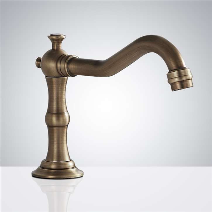
Fontana FS-354AQ-DP Antique Commercial Automatic Sensor Faucet:
Infrared Sensor Detection Zone Diagram
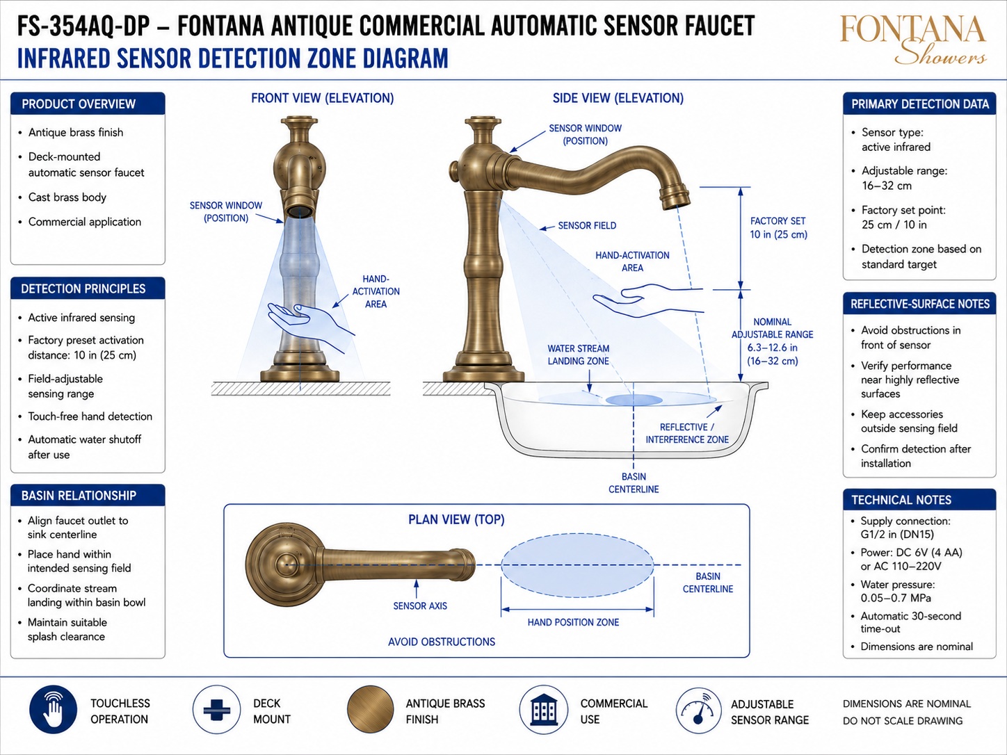
This infrared sensor detection-zone resource supports architects,
plumbing engineers, specifiers, contractors, installers and facility
teams coordinating the Fontana FS-354AQ-DP commercial automatic sensor
faucet. The diagram identifies the active-infrared sensor window,
sensor axis, hand-activation area, adjustable detection range,
factory sensing distance, basin centerline, water-stream landing zone
and potential reflective or interference areas that should be evaluated
during installation and commissioning.
FS-354AQ-DP Active Infrared Detection System
The FS-354AQ-DP incorporates an active infrared sensing system
within the faucet body to provide touch-free activation. The
sensor projects a defined detection field toward the intended
hand position beneath and forward of the spout. The detection
range can be adjusted between 16 and 32 cm, while the supplied
diagram identifies a nominal factory setting of approximately
25 cm. Final sensing performance should be confirmed after the
faucet, basin and surrounding finishes are installed.
-
Model:
FS-354AQ-DP
-
Fixture type:
Commercial automatic sensor faucet
-
Installation:
Deck mounted
-
Finish:
Antique brass
-
Body construction:
Cast brass
-
Sensor type:
Active infrared
-
Activation:
Touch-free hand detection
-
Adjustable sensing range:
16–32 cm (6.3–12.6 in)
-
Factory sensing set point:
Approximately 25 cm (10 in)
-
Detection reference:
Standard target
-
Supply connection:
G1/2 in (DN15)
-
Water pressure:
0.05–0.7 MPa
-
Power:
DC 6V (4 × AA) or AC 110–220V
-
Automatic timeout:
30 seconds
-
Installation verification:
Confirm final detection after fixture installation
Required Infrared Sensor Detection Drawing Package
The sensor-detection drawing should establish the location and
orientation of the infrared sensor window relative to the faucet
body, spout, countertop and basin. Front, side and plan views
should define the sensor axis, intended hand-activation envelope,
adjustable sensing range, nominal factory setting and relationship
between the detection field and water-stream landing zone.
Reflective surfaces, accessories and other potential obstructions
should also be considered before the final sensor setting is approved.
Infrared Sensor Detection Zone Diagram
Shows the complete sensing relationship for the FS-354AQ-DP,
including the active-infrared sensor window, projected detection
field, hand-activation area, adjustable detection distance,
basin centerline, water-stream landing zone and reflective
interference area.
Sensor Window Position
The infrared sensor window is integrated into the upper
faucet body near the spout connection. Its orientation
establishes the sensing direction and should remain
unobstructed after installation.
Active Infrared Sensor Field
The sensor projects an active-infrared detection field
forward and downward toward the user's intended hand
position. Activation occurs when a suitable target enters
the configured sensing zone.
Factory Detection Set Point
The supplied detection drawing identifies an approximate
factory activation distance of 25 cm (10 in). This value
serves as the initial sensing reference before site-specific
adjustment and commissioning.
Adjustable Detection Range
The sensor range can be adjusted nominally between
16 and 32 cm (6.3–12.6 in). The final setting should
provide reliable hand detection without creating unwanted
activation from surrounding surfaces or nearby objects.
Hand-Activation Area
The intended hand position lies beneath and forward of
the faucet spout within the projected sensing envelope.
The detection field should permit natural hand placement
while keeping the activation zone coordinated with the basin.
Sensor Axis & Plan View
The plan view establishes the sensor axis along the
faucet and basin centerline and identifies the intended
hand-position zone. Accessories or other obstructions
should not project into this sensing path.
Basin & Water-Stream Relationship
Coordinate the faucet outlet, sensor axis and basin
centerline so the user activates the faucet while the
resulting water stream lands within the usable bowl area.
Maintain sufficient clearance to limit unintended splash.
Reflective-Surface Interference Zone
Highly reflective basin surfaces or objects located
within the projected sensor field may affect detection.
The completed installation should therefore be tested
with the actual basin, countertop and surrounding finishes
before the sensor adjustment is finalized.
Engineering note:
The infrared detection field shown is a coordination and commissioning
reference and should not be treated as a fixed physical boundary.
The nominal adjustable range is 16–32 cm, with approximately
25 cm identified as the factory set point. Confirm actual detection
performance after installation using the completed basin, countertop,
faucet position and surrounding finish conditions.
Sensor & Basin Coordination Considerations
Faucet-to-Basin Alignment
Align the faucet outlet and sensor axis with the intended
basin centerline so user hand placement and water delivery
occur within the usable sink area.
Hand Position
Position the active sensing zone where normal handwashing
motions naturally enter the field without requiring the
user to reach excessively toward the backsplash or drain.
Water-Stream Landing
Coordinate the detection field with the faucet outlet so
activation occurs while the water stream lands within the
bowl rather than against the backsplash, rim or countertop.
Reflective Surfaces
Verify sensor performance near polished, glossy or highly
reflective basin surfaces. Adjust the sensing distance
where necessary to avoid unintended activation or unstable
detection behavior.
Sensor Obstructions
Keep soap dispensers, accessories, trim elements and
other objects outside the intended sensor field and
away from the direct sensing axis.
Final Commissioning
Test the faucet after the basin, countertop and surrounding
finishes are complete. Confirm reliable hand detection,
appropriate shutoff and absence of nuisance activation.
Infrared Detection System Components & Functions
Sensor Setup & Commissioning Requirements
-
Sensor Type
The supplied technical diagram identifies the FS-354AQ-DP
as using active infrared sensing for touch-free hand detection.
-
Factory Detection Distance
The nominal factory sensing distance shown is approximately
25 cm (10 in), based on a standard detection target.
-
Field-Adjustable Range
The detection range can be adjusted between approximately
16 and 32 cm (6.3–12.6 in) to suit the installed
faucet and basin relationship.
-
Detection-Zone Clearance
Keep permanent fixtures, accessories and obstructions out
of the intended sensor axis and hand-position zone.
-
Reflective-Surface Check
Commission the sensor with the actual basin and surrounding
finishes installed, particularly where highly reflective
surfaces occur within or near the sensing field.
-
Water-Supply Requirement
The technical diagram identifies a G1/2 in (DN15)
water-supply connection and an operating water-pressure
range of 0.05–0.7 MPa.
-
Power Configuration
The automatic sensor system supports DC 6V using four
AA batteries or an AC 110–220V power configuration.
-
Automatic Timeout
The supplied technical drawing identifies an automatic
30-second timeout to terminate continuous activation.
Project verification:
The infrared sensor detection-zone diagram is a coordination and
commissioning resource and should not be scaled. Before final
installation, verify the active-infrared sensor orientation,
16–32 cm adjustable detection range, approximately 25 cm factory
set point, faucet and basin centerline relationship, intended
hand-activation area, water-stream landing zone, potential reflective
surfaces, nearby accessories and obstructions, G1/2 / DN15 supply
connection, 0.05–0.7 MPa water pressure, selected power arrangement
and automatic timeout against the approved project requirements.
Final detection performance should be tested after all countertop,
basin and surrounding finish work is complete.
|
|
|