Fontana Commercial Sensor Faucets™ | Architectural and Engineering Resource
Fontana FS-354AQ-DP Antique Commercial Automatic Sensor Faucet:
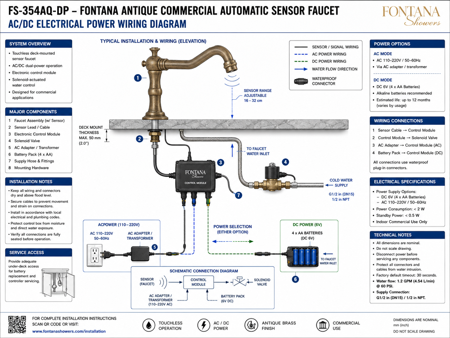
AC/DC Electrical Power Wiring Diagram
This AC/DC electrical power wiring resource supports architects,
electrical engineers, plumbing engineers, specifiers, contractors,
installers and facility teams coordinating the Fontana FS-354AQ-DP
commercial automatic sensor faucet. The diagram identifies the faucet
sensor, sensor lead, electronic control module, solenoid valve,
AC adapter / transformer, DC battery pack, waterproof plug-in connectors,
supply hose and the selectable AC or DC power path required for
touchless faucet operation.

FS-354AQ-DP AC/DC Sensor Faucet Control Architecture
The FS-354AQ-DP uses an electronic control architecture in which
the faucet sensor communicates with a below-deck control module,
which in turn operates the solenoid valve controlling water flow.
The system can be configured for AC operation through an
AC adapter / transformer or for DC operation using a 6V battery
pack containing four AA batteries. Waterproof plug-in connectors
are used at the principal electrical interfaces shown in the
technical wiring diagram.
-
Model:
FS-354AQ-DP
-
Fixture type:
Commercial automatic sensor faucet
-
Installation:
Deck mounted
-
Power architecture:
AC/DC dual-power operation
-
AC input:
110–220V, 50–60Hz
-
AC interface:
AC adapter / transformer to control module
-
DC power:
6V
-
DC battery configuration:
4 × AA batteries
-
Battery recommendation:
Alkaline batteries
-
Estimated battery life shown:
Up to 12 months, depending on usage
-
Power consumption:
Less than 2 W
-
Standby power:
Less than 0.5 W
-
Sensor range:
Adjustable 16–32 cm
-
Water supply:
G1/2 in (DN15) / 1/2 in NPT
-
Water flow:
1.2 GPM (4.54 L/min) at 60 PSI
-
Factory default timeout:
30 seconds
-
Application:
Indoor commercial use
Required AC/DC Electrical Wiring Drawing Package
The electrical wiring drawing should establish the complete control
sequence from the faucet sensor to the electronic control module and
from the control module to the solenoid valve. Separate AC and DC
power paths should be identified so installers can distinguish the
110–220V adapter-fed configuration from the 6V four-AA-battery
configuration. All plug-in connections, signal wiring, power wiring,
water-control components and service-access requirements should be
coordinated before the system is energized.
AC/DC Electrical Power Wiring Diagram
Shows the complete electrical and control arrangement for
the FS-354AQ-DP, including the faucet-mounted sensor,
sensor lead, electronic control module, solenoid valve,
AC adapter / transformer, DC battery pack and associated
waterproof plug-in connectors.
Faucet Sensor & Signal Wiring
The integrated faucet sensor connects to the electronic
control module through the sensor lead / cable. This
connection transmits the detection signal that initiates
automatic water-flow control when a valid target enters
the configured sensing range.
Electronic Control Module
The electronic control module serves as the central interface
between the faucet sensor, selected electrical power source
and solenoid valve. It receives the sensor signal and controls
the electrical command used to open or close the water-control
valve.
Solenoid-Valve Connection
The control module connects electrically to the solenoid
valve responsible for automatic water actuation. The
solenoid is installed in the water-supply path between the
building supply and faucet inlet so electronic commands
control water delivery.
AC Power Configuration
In AC mode, an AC 110–220V, 50–60Hz source supplies
the system through the designated AC adapter / transformer.
The low-voltage output connection from the adapter plugs
into the appropriate control-module power input.
DC Battery Configuration
In DC mode, electrical power is supplied by a 6V battery
pack containing four AA batteries. The drawing recommends
alkaline batteries and indicates an estimated battery life
of up to 12 months depending on actual faucet usage.
Selectable Power Path
The wiring diagram presents AC and DC as alternative power
options feeding the electronic control module. The selected
configuration should be coordinated with the project
electrical provisions and installed using the corresponding
supplied connection components.
Waterproof Electrical Connections
The diagram identifies waterproof plug-in connectors at
the system wiring interfaces. Connectors should be fully
seated before operation and maintained above potential
flood level and away from direct water exposure.
Power Consumption & Standby Load
The electrical specification identifies operating power
consumption of less than 2 W and standby power below
0.5 W. These values should be considered when coordinating
the faucet system with the selected project power source.
Engineering note:
Disconnect electrical power before servicing any control-system
component. Keep the sensor lead, control-module connections,
solenoid wiring, AC adapter connection and DC battery connector
dry, fully seated and protected from mechanical strain. Use the
power configuration and supplied connection components appropriate
to the installed system.
Electrical Installation & Coordination Considerations
AC Power Provision
Where AC operation is selected, coordinate an appropriate
110–220V, 50–60Hz supply location with the adapter /
transformer while keeping the electrical connection protected
from water exposure.
DC Battery Access
Where DC operation is selected, position the four-AA
battery pack where batteries can be inspected and replaced
without removing the faucet, lavatory or permanent
under-counter construction.
Waterproof Connections
Verify that all plug-in electrical connectors are fully
engaged and protected against moisture intrusion before
energizing the control system.
Cable Routing
Secure sensor and power cables to prevent movement,
pinching and strain at connectors. Route wiring clear
of sharp edges, flexible plumbing lines and moving
service components.
Control-Module Protection
Install the electronic controller in a dry below-deck
location above potential flood level and protect the
enclosure from direct water exposure and excessive
moisture.
Service Accessibility
Maintain adequate under-counter access to the control
module, battery pack, AC adapter connection, solenoid
valve and waterproof electrical connectors for testing,
maintenance and replacement.
AC/DC Electrical System Components
Electrical Wiring & Power Requirements
-
Sensor Cable → Control Module
The faucet sensor connects directly to the electronic
control module through the dedicated sensor / signal cable.
-
Control Module → Solenoid Valve
The electronic control module sends the actuation signal
to the solenoid valve to initiate and terminate water flow.
-
AC Adapter → Control Module
For AC operation, the 110–220V, 50–60Hz source feeds
the supplied adapter / transformer, which connects to the
designated AC input of the electronic controller.
-
Battery Pack → Control Module
For DC operation, the 6V four-AA battery pack connects
to the designated DC input of the control module.
-
Waterproof Plug-In Connections
The wiring interfaces shown use waterproof plug-in
connectors. Verify that each connector is fully seated
and protected from moisture before operation.
-
Power Consumption
The supplied diagram identifies operating power consumption
of less than 2 W and standby consumption below 0.5 W.
-
Adjustable Sensor Range
The infrared sensor range is identified as adjustable
between 16 and 32 cm.
-
Automatic Timeout
The supplied diagram identifies a factory-default
automatic timeout of 30 seconds.
Project verification:
The AC/DC electrical power wiring diagram is a coordination resource
and should not be scaled. Before installation or energization, verify
the selected AC 110–220V, 50–60Hz or DC 6V four-AA power
configuration, control-module connections, sensor lead, solenoid-valve
wiring, waterproof plug-in connectors, power consumption, standby
load, 16–32 cm adjustable sensor range, G1/2 / DN15 water
connection, supply-hose routing, under-counter service access and
30-second factory-default timeout against the approved project
requirements. Disconnect power before servicing and protect all
electrical components from water intrusion.
|
|
|