Fontana Commercial Sensor Faucets™ | Architectural and Engineering Resource
Fontana FS-354AQ-DP Antique Commercial Automatic Sensor Faucet:
Battery Pack and Backup Power Configuration
This battery-pack and backup-power resource supports architects,
electrical engineers, plumbing engineers, specifiers, contractors,
installers and facility teams coordinating the DC power arrangement
for the Fontana FS-354AQ-DP commercial automatic sensor faucet.
The diagram identifies the four-AA battery pack, waterproof battery
enclosure, polarity requirements, control module, low-battery
indicator, waterproof cable connection, solenoid-valve interface,
sensor connection and under-counter service clearances required
for battery replacement and routine maintenance.

FS-354AQ-DP DC Battery Power Assembly
The FS-354AQ-DP battery configuration uses four AA alkaline
batteries arranged in a dedicated waterproof battery pack to
provide nominal DC 6V power to the electronic control module.
The battery pack connects through a waterproof cable interface,
while the control module receives the faucet sensor signal and
controls the solenoid valve responsible for water activation.
A red low-battery indicator provides a visual maintenance signal
when battery replacement is required.
-
Model:
FS-354AQ-DP
-
Fixture type:
Commercial automatic sensor faucet
-
Installation:
Deck mounted
-
Battery type:
AA alkaline
-
Battery quantity:
4 × AA
-
Nominal battery output:
DC 6V
-
Operating voltage:
DC 4.8–6.6V
-
Operating power:
≤1.5 W
-
Standby power:
≤0.5 mW
-
Low-battery indication:
Red LED
-
Battery-pack protection:
IPX6
-
Battery connection:
Waterproof connector
-
Battery compartment:
Removable cover with polarity markings
-
Minimum front service clearance:
200–300 mm (7.87–11.81 in)
-
Control component:
Electronic control module with low-battery indicator
-
Water-control component:
Solenoid valve
Required Battery-Pack & Backup-Power Drawing Package
The battery-power drawing should establish the complete DC power
path from the four-AA battery pack to the electronic control module
and associated sensor-operated water-control components. The
battery enclosure, polarity orientation, waterproof connector,
low-battery indicator, sensor cable, solenoid connection and
service-access zone should be clearly identified. The battery pack
and controller should remain accessible after completion of the
countertop, basin and surrounding cabinetry.
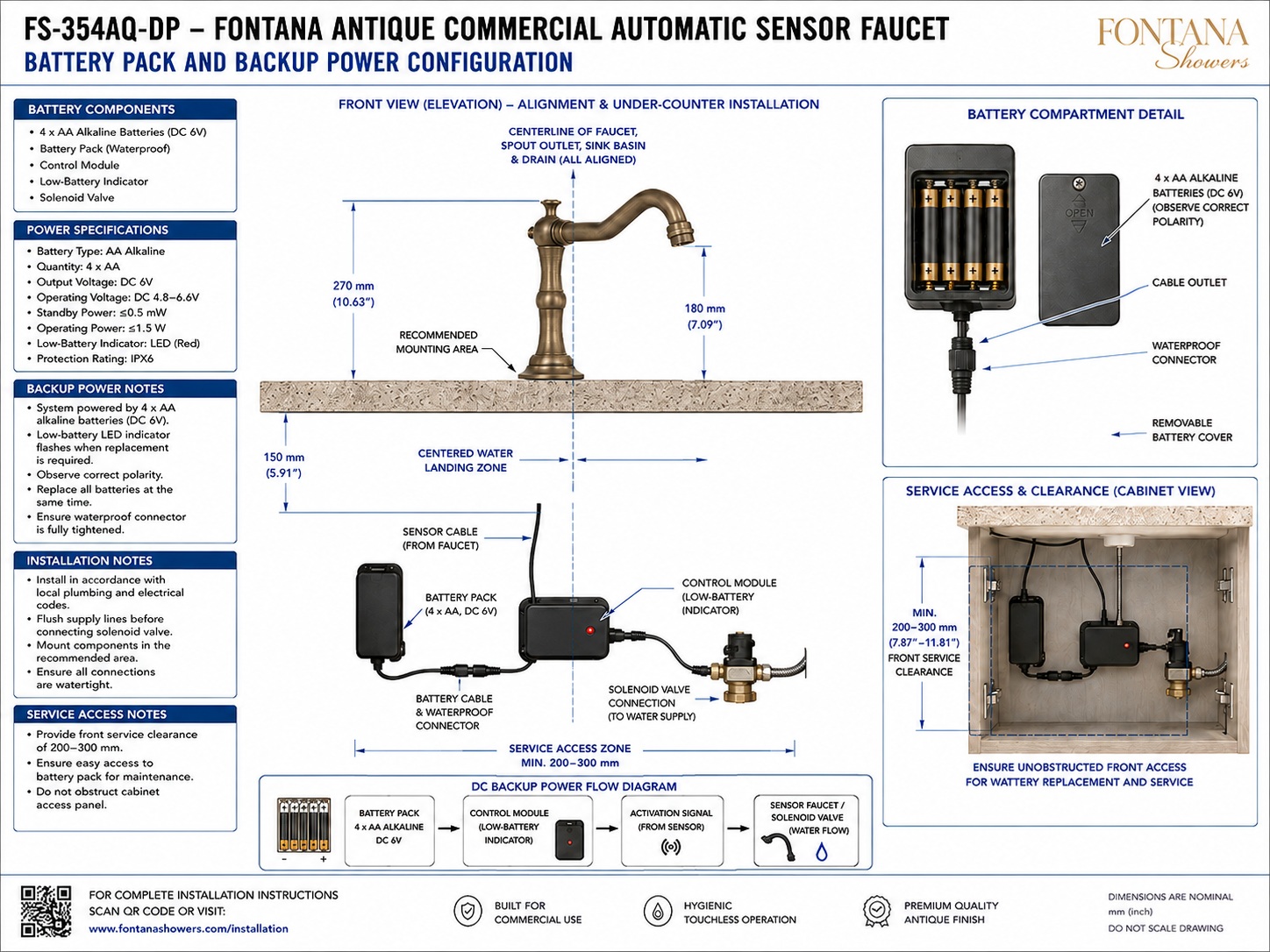
Battery Pack & Backup Power Configuration
Shows the complete DC power arrangement serving the
FS-354AQ-DP, including the four-AA alkaline battery pack,
waterproof connector, electronic control module,
low-battery indicator, faucet sensor cable, solenoid-valve
connection and required under-counter service space.
Four-AA Battery Pack
The battery enclosure accepts four AA alkaline batteries
to provide nominal DC 6V power. All four batteries should
be installed according to the polarity markings inside
the compartment and replaced as a complete set when
required.
Battery Compartment Detail
The detailed view identifies the internal four-battery
arrangement, removable battery cover, cable outlet and
waterproof connector. Positive and negative polarity
markings should be observed during battery installation
or replacement.
DC Operating Voltage
The battery-powered configuration is identified with a
nominal DC 6V output and an operating-voltage range of
DC 4.8–6.6V. The battery pack feeds the electronic
control module through the designated waterproof
connection.
Control Module
The electronic control module receives power from the
battery pack and the activation signal from the faucet
sensor. It then controls the solenoid-valve operation
required to initiate and terminate water flow.
Low-Battery Indicator
A red low-battery LED is identified on the control
module. When the indicator signals insufficient battery
condition, the four AA batteries should be replaced
together rather than mixing new and depleted cells.
Waterproof Battery Connection
The battery cable terminates at a waterproof plug-in
connector between the battery pack and control system.
The connector should be fully engaged and tightened
before operation to maintain the intended protected
connection.
Solenoid-Valve Interface
The control module communicates with the solenoid valve
in the water-supply path. After the sensor detects a valid
hand position, battery-supplied electrical power enables
the controller to actuate the solenoid and regulate water
flow to the faucet.
Service Access & Clearance
The diagram identifies a front service-access zone of
approximately 200–300 mm (7.87–11.81 in). Maintain
unobstructed access to the battery cover, connector,
control module and solenoid assembly for routine inspection
and battery replacement.
Engineering note:
The battery pack should be installed in an accessible location
below the countertop and protected from unnecessary mechanical
damage. Observe battery polarity, replace all four batteries at
the same time, fully secure the waterproof connector and maintain
the required front service-clearance zone for inspection and
maintenance.
Battery Installation & Service Coordination Considerations
Battery Polarity
Install each AA battery according to the positive and
negative polarity markings inside the battery compartment.
Incorrect orientation can prevent proper system operation.
Complete Battery Replacement
When replacement is required, replace all four AA
batteries at the same time. Do not mix batteries of
different ages or charge conditions within the pack.
Waterproof Connector
Ensure the battery cable connector is fully seated and
tightened before operation. Keep the connection protected
from unnecessary water exposure during installation and
routine service.
Low-Battery Monitoring
Monitor the red low-battery indicator on the control
module during facility maintenance. A low-battery
indication signals that battery replacement is required.
Battery-Pack Access
Locate the battery enclosure where its removable cover
can be opened without disturbing the faucet, basin,
control module, plumbing connections or permanent
cabinet construction.
Front Service Clearance
Provide approximately 200–300 mm (7.87–11.81 in)
of unobstructed front access around the below-counter
components for battery replacement, inspection and
controller servicing.
Battery & Backup-Power System Components
DC Power & Maintenance Requirements
-
Battery Type & Quantity
The supplied configuration specifies four AA alkaline
batteries installed within the dedicated battery enclosure.
-
DC Output
The four-cell battery pack provides nominal DC 6V output,
with the supplied diagram identifying an operating-voltage
range of DC 4.8–6.6V.
-
Power Demand
The technical drawing identifies operating power of
≤1.5 W and standby power of ≤0.5 mW.
-
Battery-Pack Protection
The battery enclosure is identified with an IPX6 protection
rating and a waterproof plug-in cable connection.
-
Low-Battery Indication
A red LED on the control module indicates when the battery
pack requires maintenance or replacement.
-
DC Power Flow
The illustrated sequence is:
4 × AA battery pack → electronic control module →
sensor activation/control signal → solenoid valve →
faucet water-flow operation.
-
Service Clearance
Maintain approximately 200–300 mm (7.87–11.81 in)
of unobstructed front access to the battery pack and
associated below-counter control components.
-
Battery Replacement
Observe correct polarity and replace all four batteries
at the same time. Ensure the waterproof connector is
fully secured before returning the faucet to service.
Project verification:
The battery-pack and backup-power configuration is a coordination
and maintenance resource and should not be scaled. Before installation
or commissioning, verify the four-AA alkaline battery requirement,
nominal DC 6V output, DC 4.8–6.6V operating range, ≤1.5 W
operating power, ≤0.5 mW standby power, battery polarity,
IPX6 battery enclosure, waterproof connector, red low-battery
indicator, control-module connection, sensor cable, solenoid-valve
interface and required 200–300 mm front service clearance against
the approved project requirements. Keep battery and control components
accessible for inspection and replacement.
|
|
|