Fontana Commercial Sensor Faucets™ | Architectural and Engineering Resource
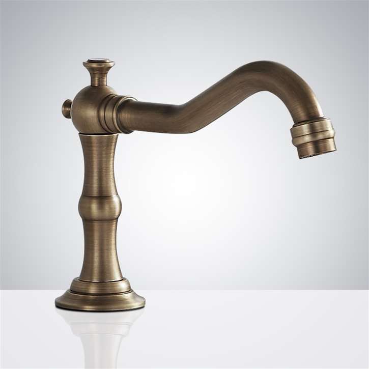
Fontana FS-354AQ-DP Antique Commercial Automatic Sensor Faucet:
Filter, Strainer, and Solenoid Protection Detail
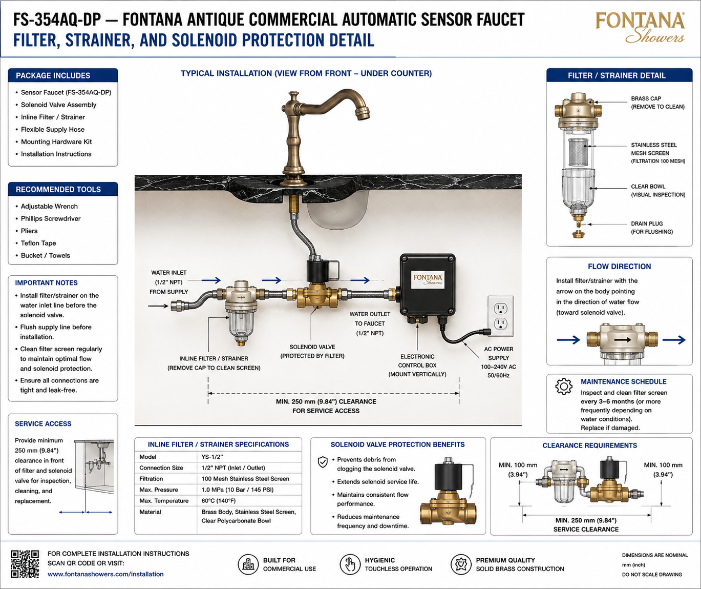
This filter, strainer and solenoid-protection resource supports plumbing
engineers, specifiers, contractors, installers and facility teams
coordinating the Fontana FS-354AQ-DP commercial automatic sensor faucet.
The drawing establishes the location of the inline filter / strainer
upstream of the solenoid valve, required water-flow direction, filtration
screen, removable cleaning cap, inspection bowl, drain plug, water inlet
and outlet connections, service clearances and maintenance requirements
intended to protect the automatic faucet's water-control components.
FS-354AQ-DP Inline Filter & Solenoid Protection Assembly
The FS-354AQ-DP protection arrangement places an inline
filter / strainer in the incoming water line before the
solenoid valve. Water entering from the building supply
first passes through the removable 100-mesh stainless-steel
screen, helping intercept debris before it can reach the
solenoid water-control assembly. The filter incorporates a
clear inspection bowl, removable brass cleaning cap and
drain plug for flushing and routine maintenance.
-
Model:
FS-354AQ-DP
-
Fixture type:
Commercial automatic sensor faucet
-
Protection component:
Inline filter / strainer
-
Filter model shown:
YS-1/2
-
Connection size:
1/2 in NPT inlet / outlet
-
Filtration:
100-mesh stainless-steel screen
-
Maximum pressure:
1.0 MPa (10 bar / 145 PSI)
-
Maximum temperature:
60°C (140°F)
-
Filter body:
Brass
-
Filter screen:
Stainless steel
-
Inspection bowl:
Clear polycarbonate
-
Flow direction:
Filter arrow toward solenoid valve
-
Minimum front service clearance:
250 mm (9.84 in)
-
Minimum side clearance shown:
100 mm (3.94 in)
-
Inspection / cleaning interval:
Every 3–6 months or more frequently as water conditions require
Required Filter & Solenoid Protection Drawing Package
The protection drawing should establish the complete water path from
the building supply through the inline filter / strainer and into the
solenoid valve before water continues toward the faucet. The filter
should be shown upstream of the solenoid with the directional arrow
aligned to actual water flow. Service drawings should identify the
removable cap, filter screen, clear inspection bowl, flushing plug,
connection sizes and required access clearances for inspection,
cleaning and component replacement.
Filter, Strainer & Solenoid Protection Detail
Shows the complete protected water-supply arrangement for
the FS-354AQ-DP, including the incoming supply connection,
inline filter / strainer, solenoid valve, faucet outlet
connection, electronic control box and required under-counter
service-access area.
Inline Filter Position
Install the filter / strainer on the water inlet line
upstream of the solenoid valve. This arrangement causes
incoming supply water to pass through the filtration screen
before reaching the automatic water-control valve.
100-Mesh Filtration Screen
The filter incorporates a 100-mesh stainless-steel screen
designed to intercept particulate debris carried by the
water supply. Routine cleaning helps maintain flow while
reducing the amount of debris reaching the solenoid valve.
Flow-Direction Orientation
The directional arrow molded or marked on the filter body
should point in the actual direction of water flow. For
this installation, the arrow points from the building
supply toward the downstream solenoid valve.
Filter Cleaning Access
The filter assembly incorporates a removable brass cap
providing access to the stainless-steel mesh screen.
Maintain sufficient clearance around the assembly so the
cap and internal screen can be removed for cleaning.
Clear Inspection Bowl
The clear polycarbonate bowl provides visual access to
the filter assembly and allows maintenance personnel to
observe accumulated debris without completely dismantling
the water-supply installation.
Drain Plug & Flushing
A drain plug is located at the bottom of the filter
assembly for flushing and service. Appropriate access
should be maintained below the bowl so flushing can be
completed without interference from surrounding components.
Solenoid Protection
Locating the filter upstream of the solenoid helps reduce
the amount of supply-line debris entering the automatic
valve. This supports consistent flow performance and
reduces debris-related blockage within the valve assembly.
Service-Clearance Requirements
The drawing identifies a minimum 250 mm (9.84 in)
service-access zone in front of the filter and solenoid
assembly, together with approximately 100 mm (3.94 in)
side clearance at the ends of the installation.
Engineering note:
Install the inline filter / strainer before the solenoid valve
and orient the filter according to its indicated water-flow arrow.
Flush the building supply before final connection and maintain
unobstructed access to the removable cap, screen, clear bowl,
drain plug, flexible connections and solenoid assembly for
routine inspection and servicing.
Filter & Solenoid Coordination Considerations
Upstream Filter Location
Place the filter between the incoming building supply
and the solenoid valve so water is filtered before
entering the automatic valve assembly.
Flow Arrow
Verify that the arrow on the filter body points toward
the solenoid valve. Reverse installation should be
avoided because it does not follow the specified
water-flow orientation.
Supply-Line Flushing
Flush debris from the building water line before
connecting the filter and solenoid assembly to reduce
the initial contamination load entering the filter.
Screen Cleaning
Inspect and clean the 100-mesh stainless-steel screen
at regular intervals. Increase maintenance frequency
where supply-water conditions produce greater sediment
or particulate loading.
Connection Integrity
Verify that all 1/2-inch NPT supply, filter, solenoid
and faucet-side connections are properly assembled,
supported and leak-free before returning the faucet
to normal operation.
Service Access
Maintain at least 250 mm (9.84 in) of clear service
space so maintenance personnel can reach the filter,
screen, bowl and solenoid valve for inspection,
cleaning or replacement.
Filter, Strainer & Protection Components
Filter Maintenance & Technical Requirements
-
Filter Model
The supplied technical drawing identifies the inline
filter / strainer as model YS-1/2.
-
Connection Size
The filter inlet and outlet are identified as
1/2-inch NPT connections.
-
Filtration
The assembly uses a 100-mesh stainless-steel filtration
screen located inside the clear inspection bowl.
-
Maximum Pressure
The filter specification identifies a maximum operating
pressure of 1.0 MPa, equivalent to 10 bar or 145 PSI.
-
Maximum Temperature
The supplied filter specification identifies a maximum
water temperature of 60°C (140°F).
-
Filter Materials
The filter assembly is identified with a brass body,
stainless-steel screen and clear polycarbonate bowl.
-
Inspection & Cleaning Interval
Inspect and clean the filter screen approximately every
3–6 months, or more frequently where local water
conditions require additional maintenance.
-
Replacement
Inspect the screen and filter components during maintenance
and replace damaged components as required.
Project verification:
The filter, strainer and solenoid-protection detail is a
coordination and maintenance resource and should not be scaled.
Before installation, verify the YS-1/2 filter configuration,
1/2-inch NPT inlet and outlet connections, 100-mesh
stainless-steel screen, 1.0 MPa / 145 PSI maximum pressure,
60°C / 140°F maximum temperature, indicated water-flow direction,
filter location upstream of the solenoid valve, 250 mm minimum
service clearance, 100 mm side clearances and access required
for cap removal, filter-screen cleaning, bowl inspection and flushing.
Flush the supply line before final connection and inspect all
completed fittings for leakage before placing the faucet into service.
|
|
|