Fontana Commercial Sensor Faucets™ | Architectural and Engineering Resource
Fontana FS-354AQ-DP Antique Commercial Automatic Sensor Faucet:
Water Pressure & Flow Requirements Diagram
This water-pressure and flow-requirements resource supports architects,
plumbing engineers, specifiers, contractors, installers and facility
teams coordinating the Fontana FS-354AQ-DP commercial automatic sensor
faucet. The diagram establishes the building-supply pressure, shut-off
valve, inline filter / strainer, solenoid valve, faucet inlet, pressure-loss
measurement points, required flow performance, supply connection and
commissioning checks needed to verify reliable faucet operation.
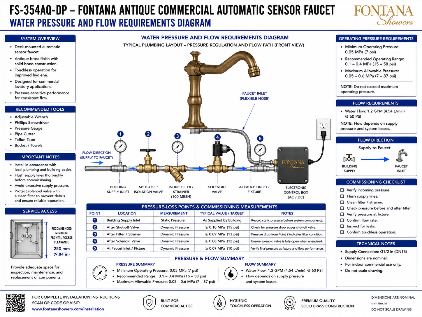
FS-354AQ-DP Pressure-Regulated Water Supply System
The FS-354AQ-DP water-supply arrangement routes incoming
building water through an isolation valve, inline 100-mesh
filter / strainer and solenoid valve before reaching the
faucet inlet. Pressure measurements at successive points in
the system allow installers to identify pressure loss across
individual components and confirm that adequate dynamic
pressure remains available at the fixture for the specified
flow performance.
-
Model:
FS-354AQ-DP
-
Fixture type:
Commercial automatic sensor faucet
-
Installation:
Deck mounted
-
Supply connection:
G1/2 in (DN15)
-
Minimum operating pressure:
0.05 MPa (7 psi)
-
Recommended operating range:
0.1–0.4 MPa (15–58 psi)
-
Maximum allowable pressure shown:
0.05–0.6 MPa (7–87 psi)
-
Rated water flow:
1.2 GPM (4.54 L/min) at 60 PSI
-
Filter / strainer:
100 mesh
-
Pressure Point 1:
Building supply inlet
-
Pressure Point 2:
After shut-off / isolation valve
-
Pressure Point 3:
After inline filter / strainer
-
Pressure Point 4:
After solenoid valve
-
Pressure Point 5:
At faucet inlet / fixture
-
Minimum service clearance:
250 mm (9.84 in)
Required Water Pressure & Flow Drawing Package
The pressure and flow drawing should identify the complete hydraulic
path from the building water supply to the faucet inlet and establish
measurement points before and after major system components. Pressure
should be checked at the building inlet, downstream of the isolation
valve, downstream of the filter / strainer, downstream of the solenoid
valve and at the fixture inlet. These measurements allow pressure
losses to be evaluated during commissioning while confirming that the
faucet receives adequate operating pressure and flow.
Water Pressure & Flow Requirements Diagram
Shows the complete supply path serving the FS-354AQ-DP
from the building inlet through the shut-off valve,
100-mesh strainer and solenoid valve to the faucet inlet.
Five pressure-measurement locations are identified for
commissioning and system-performance verification.
Point 1 – Building Supply Inlet
Point 1 establishes the upstream static-pressure reference
before the faucet system components. The drawing identifies
the target value as the pressure supplied by the building
plumbing system and uses this reading as the baseline for
subsequent pressure-loss evaluation.
Point 2 – After Isolation Valve
Point 2 measures dynamic pressure immediately downstream
of the shut-off / isolation valve. The diagram identifies
a typical target of at least 0.10 MPa (15 psi) and uses
the difference between Points 1 and 2 to identify pressure
loss through the shut-off valve.
Point 3 – After Filter / Strainer
Point 3 measures dynamic pressure downstream of the
100-mesh inline filter / strainer. The indicated target
is at least 0.09 MPa (13 psi). Pressure loss between
Points 2 and 3 can provide an indication of filter
condition during commissioning or maintenance.
Point 4 – After Solenoid Valve
Point 4 measures dynamic pressure downstream of the
solenoid valve. The drawing identifies a target of at
least 0.08 MPa (12 psi). This measurement helps verify
that the energized solenoid valve is fully open and
not creating excessive pressure loss.
Point 5 – Faucet Inlet / Fixture
Point 5 measures the final dynamic pressure available
at the faucet inlet. The drawing identifies a target of
at least 0.07 MPa (10 psi) at this location to verify
final pressure availability and faucet performance.
Recommended Operating Pressure
The supplied diagram identifies a minimum operating
pressure of 0.05 MPa (7 psi) and a recommended
operating range of 0.1–0.4 MPa (15–58 psi).
The indicated maximum operating-pressure information
should be observed during system design and commissioning.
Rated Water Flow
The faucet flow requirement is identified as
1.2 GPM (4.54 L/min) at 60 PSI. Actual delivered
flow can vary with available supply pressure and
pressure losses through valves, filters, hoses,
fittings and other components in the water path.
Service & Commissioning Access
The installation should provide approximately 250 mm
(9.84 in) of minimum frontal access to the plumbing
components so gauges, isolation devices, filter,
solenoid valve and associated connections can be
inspected, tested and serviced.
Engineering note:
Pressure should be measured under the appropriate static or
dynamic condition identified for each test point. Compare
readings across adjacent components to identify abnormal
pressure loss through the isolation valve, filter / strainer,
solenoid valve, flexible hose or fittings. Flow performance
should be confirmed only after the supply lines have been
flushed and the filtration components are clean.
Pressure & Flow Coordination Considerations
Supply Pressure
Verify available building water pressure before
commissioning the faucet. The supplied diagram identifies
0.05 MPa (7 psi) as the minimum operating pressure.
Recommended Pressure Range
The drawing identifies a recommended operating-pressure
range of 0.1–0.4 MPa (15–58 psi) for the faucet
supply system.
Filter Pressure Loss
Compare pressure immediately before and after the
100-mesh filter / strainer. An increased pressure
drop can indicate that the screen requires inspection
or cleaning.
Solenoid Pressure Loss
Measure downstream pressure while the solenoid is
energized. Excessive pressure reduction across the
valve may indicate restricted flow or incomplete
valve opening.
Fixture Pressure
Verify the final dynamic pressure at the faucet inlet
after accounting for upstream valves, filtration,
fittings and hose losses. The supplied target at this
location is at least 0.07 MPa (10 psi).
Flow Verification
Confirm actual water flow after supply pressure and
component condition have been verified. The supplied
rating is 1.2 GPM (4.54 L/min) at 60 PSI.
Pressure-Loss Measurement Points
Commissioning & Technical Requirements
-
Verify Incoming Pressure
Measure the building supply pressure before evaluating
downstream components and confirm that sufficient pressure
is available for faucet operation.
-
Flush Supply Lines
Flush the building water supply thoroughly before
commissioning to remove debris that could restrict the
filter, solenoid valve or faucet waterways.
-
Clean Filter / Strainer
Inspect the 100-mesh filter / strainer and clean the
screen where required before final pressure and flow
measurements are recorded.
-
Check Pressure Before & After Filter
Compare Points 2 and 3 to identify pressure drop across
the filter / strainer and evaluate whether the filter
condition is affecting system performance.
-
Verify Pressure at Fixture
Measure dynamic pressure at the faucet inlet after the
upstream components have been checked and confirm the
final pressure available to the fixture.
-
Confirm Flow Rate
The supplied drawing identifies a faucet flow rate of
1.2 GPM (4.54 L/min) at 60 PSI. Actual flow depends
on supply pressure and system losses.
-
Inspect for Leaks
Check the building inlet, shut-off valve, filter,
solenoid valve, flexible hose and faucet-side connections
for leakage during commissioning.
-
Confirm Touchless Operation
After pressure and flow have been verified, activate
the sensor faucet and confirm consistent automatic water
delivery and shutoff.
Project verification:
The water-pressure and flow-requirements diagram is a coordination
and commissioning resource and should not be scaled. Before placing
the faucet into service, verify the G1/2 in (DN15) supply connection,
0.05 MPa (7 psi) minimum operating pressure, 0.1–0.4 MPa
(15–58 psi) recommended operating range, maximum-pressure information
shown on the approved drawing, 1.2 GPM (4.54 L/min) rated flow
at 60 PSI, pressure at all five measurement points, isolation-valve
operation, 100-mesh filter condition, solenoid-valve operation,
250 mm minimum frontal service clearance and all connections for
leakage. Actual flow should be evaluated against available supply
pressure and pressure losses through the installed system.
|
|
|