Fontana Commercial Sensor Faucets™ | Architectural and Engineering Resource
Fontana FS-354AQ-DP Antique Commercial Automatic Sensor Faucet:
Automatic Operating Sequence & Control Logic
This automatic operating-sequence and control-logic resource supports
architects, plumbing engineers, electrical engineers, specifiers,
contractors, installers and facility teams coordinating the Fontana
FS-354AQ-DP commercial automatic sensor faucet. The diagram establishes
the complete sequence from standby monitoring and infrared hand detection
through electronic signal processing, solenoid-valve actuation, water
delivery, hand removal and automatic shutoff. It also identifies the
adjustable sensing range, response timing, automatic timeout protection,
AC/DC power options and principal interaction between the sensor,
electronic control module and solenoid valve.

FS-354AQ-DP Automatic Sensor Control Sequence
The FS-354AQ-DP operates through an infrared sensor, electronic
control module and electrically actuated solenoid valve. During
standby, the faucet continuously monitors its configured detection
zone. When a user's hand enters the sensing field, the sensor
transmits an activation signal to the controller. The controller
processes the signal and energizes the solenoid valve, allowing
water to flow. When the hand leaves the sensing zone, the signal
ends and the valve closes automatically.
-
Model:
FS-354AQ-DP
-
Fixture type:
Commercial automatic sensor faucet
-
Sensor technology:
Infrared touchless detection
-
Detection distance:
Adjustable 16–32 cm (6.3–12.6 in)
-
Response time:
Less than 1 second
-
Shutoff after hand removal:
Less than 2 seconds
-
Automatic timeout:
30 seconds, factory default
-
Sensor connection:
Sensor cable to electronic control module
-
Water-control component:
Solenoid valve
-
Control component:
Electronic control module
-
Power:
DC 6V (4 × AA) or AC 110–220V, 50–60Hz
-
Water flow:
1.2 GPM (4.54 L/min) at 60 PSI
-
Supply connection:
G1/2 in (DN15)
-
Recommended front service clearance:
250–300 mm (9.8–11.8 in)
-
Application:
Indoor commercial use
Required Automatic Operating Sequence & Control Logic Drawing Package
The control-logic drawing should establish the complete operational
sequence from standby monitoring to automatic water shutoff. The
infrared sensor, detection zone, sensor cable, electronic controller,
solenoid valve, water inlet and selected power source should be shown
as an integrated system. Response timing, sensing distance, shutoff
timing and automatic timeout protection should also be identified so
the system can be tested during commissioning and future maintenance.
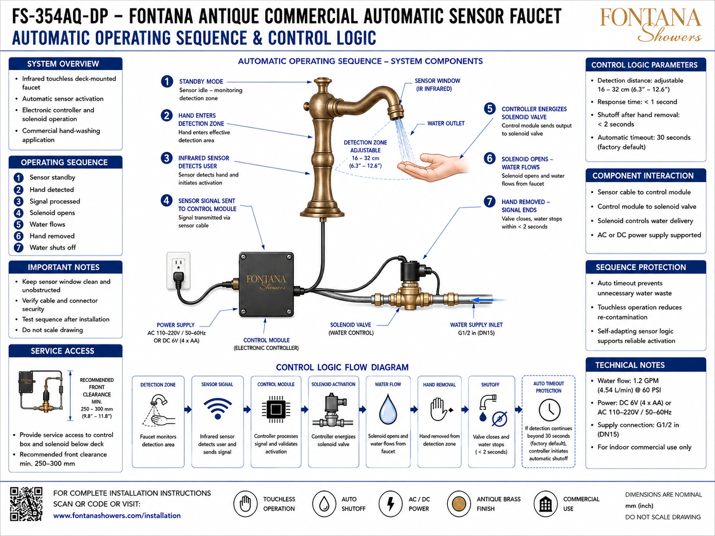
Automatic Operating Sequence & Control Logic
Shows the complete operating sequence for the FS-354AQ-DP
from sensor standby through user detection, signal processing,
solenoid activation, water flow, hand removal and automatic
shutoff. The diagram also identifies the controller, water
supply and AC/DC power architecture.
1. Sensor Standby Mode
When no valid target is present, the infrared sensor remains
in standby mode and monitors the configured detection zone.
The solenoid valve remains closed and no water is delivered
through the faucet.
2. Hand Enters Detection Zone
Operation begins when the user's hand enters the effective
infrared sensing area beneath the faucet outlet. The detection
distance can be adjusted between approximately 16 and 32 cm
(6.3–12.6 in).
3. Infrared Sensor Detects User
The infrared sensor identifies the hand within the valid
detection zone and initiates the electronic activation
sequence. The diagram identifies a response time of less
than one second.
4. Sensor Signal Sent to Controller
The activation signal travels through the sensor cable
from the faucet to the electronic control module below
the deck. The controller receives and processes the
sensor input before actuating the water-control valve.
5. Controller Energizes Solenoid
After validating the activation signal, the electronic
control module sends an electrical output to the solenoid
valve. The controller therefore serves as the interface
between the infrared sensor and water-control assembly.
6. Solenoid Opens & Water Flows
The energized solenoid valve opens the controlled water
path, allowing supply water to travel through the valve
and faucet assembly to the outlet. The supplied diagram
identifies a flow of 1.2 GPM (4.54 L/min) at 60 PSI.
7. Hand Removed & Water Shuts Off
When the user's hand leaves the detection field, the
activation signal terminates. The controller de-energizes
the solenoid valve, which closes the water path. The
diagram identifies shutoff within less than two seconds
after hand removal.
30-Second Timeout Protection
If continuous detection extends beyond the factory-default
30-second timeout, the controller initiates automatic
shutoff. This sequence protection limits unnecessary
continuous water delivery.
Engineering note:
The control sequence should be verified after installation using
the completed faucet, basin, sensor, controller, solenoid valve
and selected AC or DC power configuration. Confirm detection,
response, valve opening, water delivery, hand-removal shutoff and
30-second timeout operation before final commissioning.
Control Logic & Commissioning Considerations
Sensor Window
Keep the infrared sensor window clean and unobstructed
so the detection field can reliably identify a user's
hands within the configured sensing distance.
Sensor Cable
Verify that the sensor cable is securely connected
between the faucet and control module and that wiring
is protected from strain, sharp edges and accidental
disconnection.
Control Module
Keep the electronic controller accessible below the
counter so sensor input, power connections and solenoid
output can be inspected during testing and service.
Solenoid Response
Confirm that the solenoid valve opens promptly when
the controller receives a valid activation signal and
closes when the detection signal terminates.
Detection Range
Adjust the nominal 16–32 cm sensing range so normal
handwashing movements activate the faucet without
creating unintended sensing from nearby objects or
surfaces.
Service Access
Maintain approximately 250–300 mm (9.8–11.8 in)
of recommended front clearance for access to the
controller, solenoid valve, wiring and associated
service components.
Automatic Control-System Components
Control Logic Parameters & Operating Requirements
-
Adjustable Detection Distance
The infrared detection distance is identified as adjustable
from approximately 16 to 32 cm (6.3–12.6 in).
-
Response Time
The supplied control-logic diagram identifies a response
time of less than one second after valid user detection.
-
Hand-Removal Shutoff
After the user's hand leaves the detection field, the
supplied diagram identifies water shutoff within less
than two seconds.
-
Automatic Timeout
The controller includes a factory-default 30-second
automatic timeout if continuous detection persists.
-
Sensor-to-Controller Interaction
The faucet sensor communicates with the electronic
control module through the dedicated sensor cable.
-
Controller-to-Solenoid Interaction
The electronic control module sends the actuation
command to the solenoid valve responsible for
automatic water delivery.
-
Power Configuration
The supplied control diagram supports DC 6V power
using four AA batteries or AC 110–220V at 50–60Hz.
-
Water Supply & Flow
The diagram identifies a G1/2 in (DN15) supply
connection and rated water flow of 1.2 GPM
(4.54 L/min) at 60 PSI.
Project verification:
The automatic operating-sequence and control-logic drawing is a
coordination and commissioning resource and should not be scaled.
Before placing the faucet into service, verify the infrared sensor
window, 16–32 cm adjustable detection range, less-than-one-second
response time, sensor-cable connection, electronic control-module
operation, solenoid-valve actuation, water-flow response, less-than-two-second
shutoff after hand removal, 30-second factory-default automatic timeout,
DC 6V or AC 110–220V power arrangement, G1/2 in (DN15) supply
connection and recommended 250–300 mm front service clearance.
Test the complete operating sequence after final installation and
confirm consistent touchless activation and automatic shutoff.
|
|
|