Fontana Commercial Sensor Faucets™ | Architectural and Engineering Resource
Fontana FS-354AQ-DP Antique Commercial Automatic Sensor Faucet:
Planning Guide for Optimal Performance and Splash Control
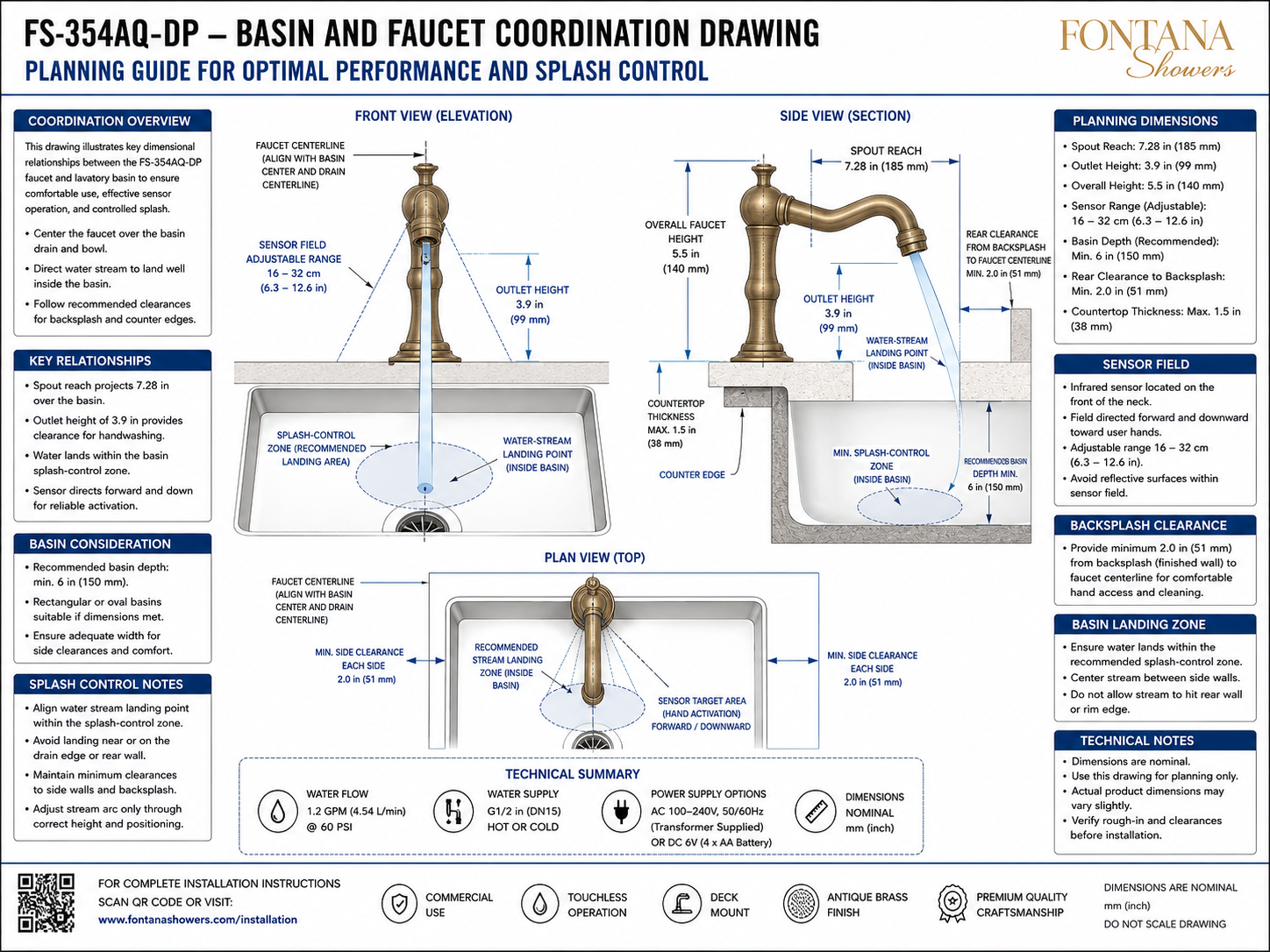
This basin-and-faucet coordination resource supports architects,
plumbing engineers, interior designers, specifiers, contractors and
installers planning the Fontana FS-354AQ-DP commercial automatic
sensor faucet with a compatible lavatory basin. The drawing establishes
the relationship between faucet centerline, basin centerline, drain,
spout reach, outlet height, infrared sensing field, water-stream landing
point, basin depth, backsplash clearance, side clearances and countertop
thickness to support effective touchless operation and controlled splash.
FS-354AQ-DP Faucet-to-Basin Coordination
The FS-354AQ-DP should be positioned so the faucet centerline,
basin center and drain centerline are coordinated as a unified
layout. The 7.28 in nominal spout reach projects the outlet over
the bowl, while the 3.9 in outlet height provides handwashing
clearance above the countertop. The water stream should land
inside the recommended splash-control zone, and the infrared
sensing field should remain unobstructed for reliable activation.
-
Model:
FS-354AQ-DP
-
Fixture type:
Commercial automatic sensor faucet
-
Installation:
Deck mounted
-
Finish:
Antique brass
-
Spout reach:
7.28 in (185 mm)
-
Outlet height:
3.9 in (99 mm)
-
Overall faucet height:
5.5 in (140 mm)
-
Adjustable sensor range:
16–32 cm (6.3–12.6 in)
-
Recommended minimum basin depth:
6 in (150 mm)
-
Minimum rear clearance to backsplash:
2.0 in (51 mm)
-
Minimum side clearance:
2.0 in (51 mm) each side
-
Maximum countertop thickness:
1.5 in (38 mm)
-
Water flow:
1.2 GPM (4.54 L/min) at 60 PSI
-
Water supply:
G1/2 in (DN15), hot or cold
-
Power options:
AC 100–240V, 50/60Hz or DC 6V with 4 × AA batteries
Required Basin & Faucet Coordination Drawing Package
The coordination drawing should establish the faucet relative to
the basin in front elevation, side section and plan view. Faucet,
basin and drain centerlines should be coordinated together, while
the spout reach, outlet height, sensor field and stream landing
position should be evaluated against the selected basin geometry.
Minimum basin depth, backsplash clearance, side clearances and
countertop thickness should be confirmed before countertop
fabrication or fixture installation.
Basin & Faucet Coordination Drawing
Provides the overall planning relationship between the
FS-354AQ-DP faucet, countertop and lavatory basin.
The drawing combines elevation, section and plan views
to establish centerline alignment, sensing geometry,
water-stream placement and splash-control clearances.
Faucet & Basin Centerline
Align the faucet centerline with the basin center and
drain centerline where practical. This establishes a
consistent geometric reference for spout positioning,
sensor activation and water-stream landing.
Spout Reach
The drawing identifies a nominal spout reach of
7.28 in (185 mm). The projecting outlet should extend
sufficiently over the basin so the water stream lands
inside the bowl rather than on the rear wall or rim.
Outlet Height
The faucet outlet is shown approximately 3.9 in
(99 mm) above the countertop reference plane. This
vertical relationship provides working clearance beneath
the outlet while maintaining the intended stream trajectory.
Infrared Sensor Field
The infrared sensor is positioned at the front of the
faucet neck and projects its activation field forward
and downward toward the user's hands. The nominal sensing
range is adjustable from 16 to 32 cm (6.3–12.6 in).
Water-Stream Landing Zone
Position the faucet so the stream lands well inside the
basin within the recommended splash-control area. Avoid
directing the stream onto the rear wall, basin rim or
immediately onto the drain edge.
Basin Depth
The planning drawing recommends a minimum basin depth
of approximately 6 in (150 mm). Adequate bowl depth
provides space for the water-stream landing zone and
helps control splash during normal handwashing.
Backsplash & Rear Clearance
Maintain a minimum 2.0 in (51 mm) distance from the
backsplash or finished wall to the faucet centerline.
This clearance supports comfortable access around the
faucet and provides space for cleaning.
Plan-View Side Clearances
The plan view identifies approximately 2.0 in
(51 mm) minimum clearance on each side of the basin
coordination area. Adequate basin width should be
provided so handwashing occurs without interference
from adjacent side walls.
Engineering note:
The dimensions shown are nominal planning references and the
drawing should not be scaled. Verify actual faucet dimensions,
basin geometry, countertop thickness, rough-in location,
spout-to-basin relationship, sensor range and required clearances
before countertop fabrication or final fixture installation.
Performance & Splash-Control Coordination Considerations
Center Faucet Over Basin
Coordinate the faucet with the basin center and drain
so the fixture remains visually aligned and the stream
enters the intended portion of the bowl.
Stream Landing Point
Position the outlet so the stream lands within the
recommended splash-control zone and remains clear of
the basin rear wall, rim and drain edge.
Sensor Target Area
Maintain an unobstructed hand-activation area forward
and below the sensor window. Avoid accessories or
reflective objects that project into the active
sensing field.
Basin Depth
Use a basin with approximately 6 in (150 mm) minimum
recommended depth so the projected water stream remains
within the usable bowl and splash-control area.
Backsplash Clearance
Maintain at least 2.0 in (51 mm) between the faucet
centerline and backsplash or finished wall to preserve
operating, cleaning and hand-access clearance.
Countertop Thickness
The supplied planning drawing identifies a maximum
countertop thickness of 1.5 in (38 mm). Verify the
actual deck construction and mounting requirements
before fabrication.
Planning Dimensions & Coordination References
Optimal Performance Planning Requirements
-
Faucet, Basin & Drain Alignment
Coordinate the faucet centerline with the basin center
and drain centerline to establish consistent fixture
geometry and stream placement.
-
Water-Stream Placement
Direct the water stream well inside the basin and within
the recommended splash-control zone. Avoid landing directly
on the rear wall, rim or drain edge.
-
Basin Configuration
Rectangular or oval basins may be used where the
recommended depth, width and clearance relationships
shown in the coordination drawing are maintained.
-
Sensor Field
The infrared sensor is located at the front of the faucet
neck and directs the sensing field forward and downward.
Keep reflective surfaces and obstructions out of the
intended target area.
-
Splash Control
Control splash through proper faucet height, spout reach,
basin depth and stream landing location rather than allowing
the stream to strike surrounding basin surfaces.
-
Water Flow
The supplied planning drawing identifies a water-flow
rating of 1.2 GPM (4.54 L/min) at 60 PSI.
-
Water Supply
The technical summary identifies a G1/2 in (DN15)
connection for hot or cold water supply.
-
Power Supply Options
The drawing identifies AC 100–240V, 50/60Hz operation
through a supplied transformer or DC 6V operation using
four AA batteries.
Project verification:
The basin-and-faucet coordination drawing is a planning resource
and should not be scaled. Before countertop fabrication or
installation, verify the 7.28 in (185 mm) spout reach,
3.9 in (99 mm) outlet height, 5.5 in (140 mm) overall
faucet height, 16–32 cm adjustable sensor range, minimum
6 in (150 mm) recommended basin depth, minimum 2.0 in
(51 mm) backsplash clearance, minimum 2.0 in (51 mm)
side clearances, 1.5 in (38 mm) maximum countertop thickness,
faucet and basin centerline relationship, water-stream landing
point and splash-control zone against the actual basin,
countertop and approved project conditions.
|
|
|