Fontana Commercial Sensor Faucets™ | Architectural and Engineering Resource
Fontana FS-354AQ-DP Antique Commercial Automatic Sensor Faucet:
ADA and Accessible Installation Coordination
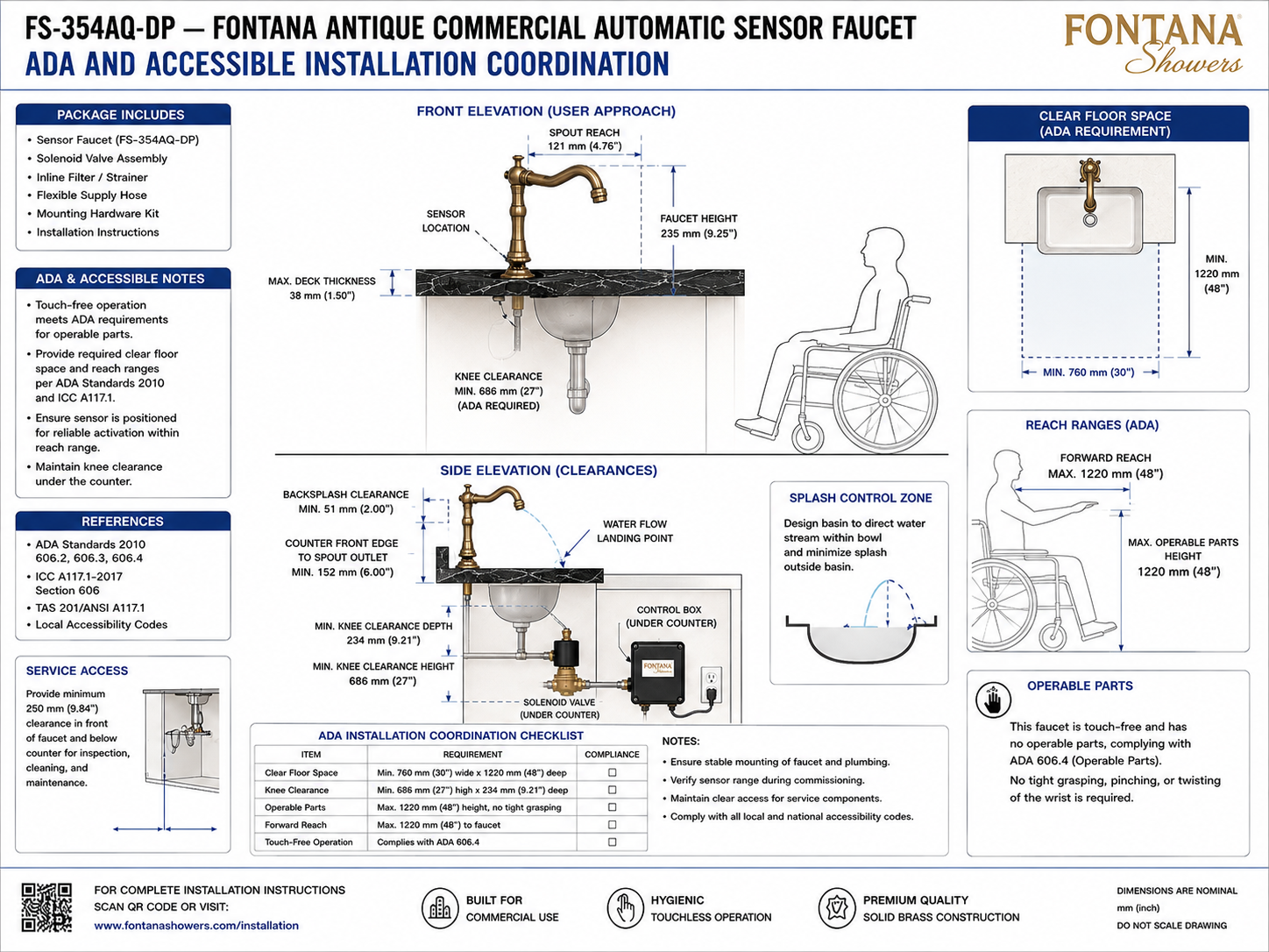
This ADA and accessible-installation coordination resource supports
architects, plumbing engineers, accessibility consultants, specifiers,
contractors and installers coordinating the Fontana FS-354AQ-DP
commercial automatic sensor faucet within accessible lavatory layouts.
The drawing identifies clear floor space, knee clearance, forward reach,
operable-parts height, faucet and basin relationships, backsplash
clearance, countertop thickness, sensor positioning, splash-control
considerations and below-counter service access required for coordinated
accessible installation planning.
FS-354AQ-DP Accessible Lavatory Coordination
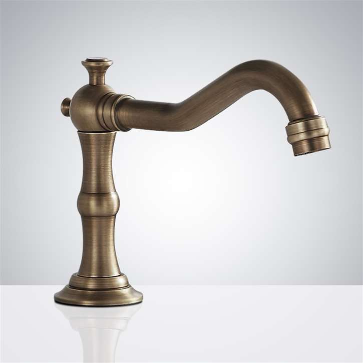
The FS-354AQ-DP is a touch-free deck-mounted sensor faucet
intended to be coordinated with the accessible lavatory,
countertop and approach area as a complete installation.
The supplied drawing illustrates wheelchair approach,
clear-floor-space requirements, knee-clearance dimensions,
forward-reach limits and the relationship between the faucet,
sensor, basin and below-counter control components.
-
Model:
FS-354AQ-DP
-
Fixture type:
Commercial automatic sensor faucet
-
Operation:
Touch-free infrared activation
-
Installation:
Deck mounted
-
Spout reach shown:
121 mm (4.76 in)
-
Faucet height shown:
235 mm (9.25 in)
-
Maximum deck thickness:
38 mm (1.50 in)
-
Minimum clear floor space:
760 mm × 1220 mm (30 × 48 in)
-
Minimum knee-clearance height:
686 mm (27 in)
-
Minimum knee-clearance depth shown:
234 mm (9.21 in)
-
Maximum forward reach shown:
1220 mm (48 in)
-
Maximum operable-parts height shown:
1220 mm (48 in)
-
Counter front edge to spout outlet:
Minimum 152 mm (6 in)
-
Backsplash clearance:
Minimum 51 mm (2 in)
-
Minimum service-access clearance:
250 mm (9.84 in)
Required ADA & Accessible Installation Drawing Package
The accessible-installation drawing should coordinate the faucet,
countertop, basin, wheelchair approach and under-counter plumbing
as a unified layout. Clear floor space, knee clearance, forward
reach and operable-parts criteria should be established relative
to the completed floor and countertop. The sensor should remain
reliably accessible within the user's approach zone, while the
below-counter solenoid, control box and plumbing components should
be located so required knee space is not unnecessarily obstructed.
ADA & Accessible Installation Coordination
Shows the complete accessible installation relationship
between the FS-354AQ-DP faucet, lavatory, countertop,
wheelchair approach, clear floor space, knee clearance,
forward reach, operable parts and below-counter equipment.
Clear Floor Space
The supplied drawing identifies a minimum clear floor
space of 760 mm (30 in) wide by 1220 mm (48 in)
deep at the accessible lavatory approach. Maintain this
area clear of permanent obstructions.
Knee-Clearance Height
The front and side elevation identifies a minimum
686 mm (27 in) knee-clearance height below the
accessible lavatory. Coordinate the basin, drain,
supply piping and control equipment so this space
is preserved.
Knee-Clearance Depth
The drawing identifies approximately 234 mm
(9.21 in) minimum knee-clearance depth within the
illustrated installation. Plumbing and electronic
components should be positioned to avoid unnecessary
encroachment into the required user space.
Forward Reach
The accessibility diagram identifies a maximum forward
reach of 1220 mm (48 in). The faucet's touch-free
operation should be coordinated so the intended user
can activate the sensor within the established approach
and reach conditions.
Touch-Free Operable Parts
The faucet is activated through infrared sensing rather
than a manual handle. The supplied drawing notes that
no tight grasping, pinching or twisting of the wrist
is required for normal faucet activation.
Sensor Position & Reach
Coordinate the sensor location with the accessible
approach so users can reliably enter the detection
field without excessive forward reach. Sensor performance
should be verified after final installation.
Faucet & Countertop Geometry
The drawing identifies a 121 mm (4.76 in) spout
reach, 235 mm (9.25 in) faucet height and maximum
38 mm (1.50 in) deck thickness. These dimensions
should be coordinated with the selected lavatory
and countertop assembly.
Splash-Control Zone
The basin should be coordinated so the faucet's
water-stream landing point remains within the bowl.
Proper stream placement helps reduce splash onto
the user, floor and surrounding countertop.
Engineering note:
Accessible fixture compliance depends on the complete installed
lavatory assembly and surrounding approach—not the faucet alone.
Verify clear floor space, knee and toe space, reach conditions,
counter height, basin geometry, exposed plumbing protection,
sensor activation and locally adopted accessibility requirements
for the completed project installation.
Accessible Installation Coordination Considerations
Wheelchair Approach
Provide the required accessible approach and maintain
the clear floor area in front of the lavatory so a
wheelchair user can position appropriately for
touch-free faucet use.
Knee Space
Coordinate the basin, trap, supply lines, solenoid valve
and control box so required knee clearance remains
available beneath the accessible countertop.
Sensor Activation
Position and commission the infrared sensor so the
user's hands can enter the activation field from the
intended accessible approach without excessive reach.
Backsplash Clearance
The supplied drawing identifies a minimum 51 mm
(2 in) backsplash-to-faucet clearance. Maintain adequate
space for hand access, cleaning and sensor performance.
Under-Counter Equipment
Locate the solenoid valve, control box, wiring and
associated connections outside critical user-clearance
areas wherever practical while retaining maintenance
access.
Service Access
Provide at least the indicated 250 mm (9.84 in)
frontal service access to faucet-control components
without compromising the required accessible approach
and knee-clearance geometry.
Accessibility Planning Criteria
ADA Installation Coordination Checklist
-
Clear Floor Space
Provide the required accessible floor space at the
lavatory approach. The supplied drawing illustrates
760 mm (30 in) minimum width by 1220 mm (48 in)
minimum depth.
-
Knee Clearance
The supplied drawing identifies approximately
686 mm (27 in) minimum knee-clearance height and
234 mm (9.21 in) minimum illustrated depth.
-
Operable Parts
The coordination drawing uses a maximum 1220 mm
(48 in) operable-parts height reference and notes
that touch-free operation requires no tight grasping,
pinching or twisting of the wrist.
-
Forward Reach
The supplied accessibility detail illustrates a maximum
1220 mm (48 in) forward-reach reference for the
faucet-user approach.
-
Touch-Free Operation
The sensor faucet is automatically activated by user
presence rather than a manually operated handle.
Confirm reliable detection from the accessible user position.
-
Water-Stream Landing
Coordinate the spout and basin so water lands well
inside the bowl and minimizes splash outside the
lavatory during normal use.
-
Sensor Commissioning
Verify the sensor range and activation response after
the final countertop, basin and surrounding finishes
have been installed.
-
Applicable Accessibility References
The supplied drawing references ADA Standards 2010
Sections 606.2, 606.3 and 606.4, ICC A117.1-2017
Section 606, TAS 201 / ANSI A117.1 and applicable
local accessibility requirements.
Project verification:
The ADA and accessible-installation coordination drawing is a
planning resource and does not by itself establish project compliance.
Before installation, verify the complete lavatory assembly,
760 mm × 1220 mm (30 × 48 in) clear floor-space requirement,
686 mm (27 in) knee-clearance height, required knee and toe
clearances, applicable reach limits, countertop height and thickness,
121 mm (4.76 in) spout reach shown, faucet-to-counter-edge
relationship, 51 mm (2 in) backsplash clearance, sensor location,
water-stream landing zone, exposed plumbing protection and
250 mm (9.84 in) service access against the project drawings,
locally adopted accessibility standards and final field conditions.
|
|
|